
DCFR Insight 31 / Data Center Delivery + Quality Control
Design Review + Owner-Side ArchitectureOwner-Side Data Center Design Reviews at 30%, 60%, 90%, and IFC
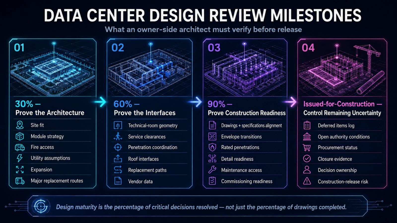
A data center design package should not advance because the drawings look more complete. It should advance only when the decisions appropriate to that milestone are resolved, coordinated, measurable, and safe to release downstream.

Design Maturity Is Decision Maturity
A 30% design review and a 90% design review should not ask the same questions. At 30%, the owner should prevent the team from developing the wrong building. At 60%, prevent disciplines from developing incompatible systems. At 90%, prevent the contractor from receiving ambiguous, incomplete, or unbuildable documents. At Issued-for-Construction, know exactly which uncertainties remain, who owns them, and whether they can affect procurement, permitting, construction, energization, commissioning, or operations. For an owner-side architect, design review is not redrawing the Architect or Engineer of Record's work. It verifies that architecture, engineering, vendor information, owner requirements, authority conditions, construction logic, maintenance strategy, and operational intent converge into one executable facility.
DESIGN MATURITY IS NOT THE PERCENTAGE OF DRAWINGS COMPLETED. IT IS THE PERCENTAGE OF CRITICAL DECISIONS THAT HAVE BEEN RESOLVED, COORDINATED, AND MADE SAFE TO RELEASE DOWNSTREAM.
Start With the Owner's Review Basis
Owner review comments need a governing basis. An owner-side review should not become: “This is how I would have designed it.” Every significant comment should trace to a requirement, risk, interface, owner objective, or unresolved decision. The owner-side architect checks physical translation and coordination without casually assuming the responsible professional's engineering duty.
Owner Review Basis
| Review Basis | What It Controls | Owner-Side Question |
|---|---|---|
| Owner's Project Requirements (OPR) | Capacity, resilience, operations, security, maintainability | Does this design still deliver what the owner bought? |
| Basis of Design (BOD) | Technical design intent and assumptions | Does the package follow the approved design basis? |
| Reference Design | Repeatable portfolio solution | Has the site adapted the reference correctly? |
| Adopted Code | Regulatory minimum requirements | Has the responsible design professional demonstrated compliance? |
| Authority Having Jurisdiction (AHJ) | Project-specific interpretation | Are unresolved authority conditions visible and owned? |
| Manufacturer Requirements | Equipment geometry, installation, operation | Does the building accommodate actual selected equipment? |
| Engineer of Record (EOR) | Discipline-specific professional design | Are engineering requirements translated into physical space and interfaces? |
| Insurer / Factory Mutual (FM) | Property-loss-prevention criteria where applicable | Are insurer-driven requirements incorporated? |
| Commissioning | Functional verification | Can the completed system actually be tested? |
| Operations | Maintainability and continuity | Can equipment be operated, isolated, serviced, and replaced? |
Use Five Technical-Basis Labels
Labels show where a requirement comes from and who confirms it. The National Fire Protection Association (NFPA) publishes the National Electrical Code (NEC) and fire-protection standards; applicability and adopted editions require project-specific confirmation. Do not write “Corridor too narrow.” Identify the route use, controlling basis, required clear dimension, and responsible confirming party. Where information is unknown, mark PROJECT-SPECIFIC CONFIRMATION REQUIRED.
Technical-Basis Labels
| Classification | Meaning |
|---|---|
| CODE / REGULATORY | Required by adopted regulation. |
| ENGINEERING | Determined by responsible design engineer. |
| MANUFACTURER | Equipment-specific installation, service, or replacement requirement. |
| OWNER STANDARD | Portfolio or project requirement established by owner. |
| DCFR PLANNING ALLOWANCE | Early planning assumption pending final design information. |
| PROJECT-SPECIFIC CONFIRMATION REQUIRED | Jurisdiction, equipment, or project information remains to be confirmed. |
30% Review — Prove the Architecture
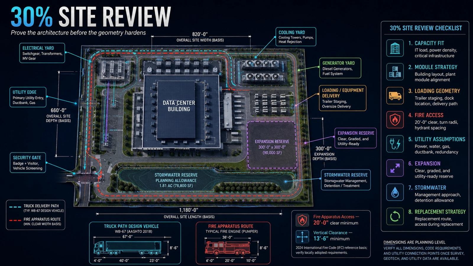
At approximately 30%, prove site fit, capacity, building module, major yards, access, utilities, expansion, fire strategy, security, stormwater, and replacement strategy. Do not spend most owner-review effort on minor room tags, finish notes, decorative elevations, or small drafting issues. Geometry is still movable; review high-cost decisions first.
30% Site Fit
Review the physical chain: parcel → buildable envelope → data center building → electrical yard → generator yard → cooling yard → loading → parking → stormwater → security → fire access → utilities → expansion.
- 1
Does target Information Technology (IT) capacity physically fit
Does target Information Technology (IT) capacity physically fit?
- 2
Is the data hall module strategy visible
Is the data hall module strategy visible?
- 3
Is future expansion protected
Is future expansion protected?
- 4
Is the utility edge understood
Is the utility edge understood?
- 5
Can major trucks enter and leave
Can major trucks enter and leave?
- 6
Is a credible loading and equipment-delivery strategy shown
Is a credible loading and equipment-delivery strategy shown?
- 7
Is stormwater consuming realistic land
Is stormwater consuming realistic land?
- 8
Are generators and cooling equipment positioned with sensitive neighbors in mind
Are generators and cooling equipment positioned with sensitive neighbors in mind?
- 9
Can major equipment eventually be replaced
Can major equipment eventually be replaced?
- 10
Does security conflict with emergency access
Does security conflict with emergency access?
- 11
Can construction staging occur
Can construction staging occur?
- 12
Are major site assumptions explicitly identified
Are major site assumptions explicitly identified?
Dimension Fire Access at 30%
CODE / REGULATORY — As a current model-code reference basis, 2024 International Fire Code (IFC) Section 503.2.1 establishes a 20'-0" minimum unobstructed fire apparatus access-road width and 13'-6" minimum unobstructed vertical clearance. This is a 2024 International Fire Code reference basis; verify the edition, amendments, fire-code official requirements, and project-specific conditions adopted by the jurisdiction. A plan should not merely show a red line labeled “FIRE ACCESS.” The preliminary route should carry real planning dimensions and identify their source. The infographic is explanatory: depicted dimensions may represent a code reference, local setback, DCFR PLANNING ALLOWANCE, or project-specific assumption and are not all universal code requirements.
Prove the Building Module at 30%
After defining megawatt (MW), a box labeled “40 MW Data Center” is insufficient. OWNER STANDARD / DCFR PLANNING ALLOWANCE — an illustrative 40 megawatt Information Technology load may become 4 × 10 megawatt data hall modules rather than one vague room. These are planning examples, not universal requirements. Identify target IT load, rack-density and rack-count bases, module capacity and quantity, support-space organization, electrical and mechanical spine, and phasing. These decisions affect structure, electrical distribution, cooling, commissioning, construction sequence, and future operation.
30% Owner-Side Release Gate
If several critical items remain open, producing more drawings does not make the project more mature. It makes redesign more expensive.
30% Owner-Side Release Gate
| Release Item | Status |
|---|---|
| Target IT capacity reconciled with building | PASS / OPEN |
| Data hall module strategy | PASS / OPEN |
| Major technical rooms | PASS / OPEN |
| Electrical yard | PASS / OPEN |
| Generator yard | PASS / OPEN |
| Cooling / heat rejection | PASS / OPEN |
| Truck / loading geometry | PASS / OPEN |
| Fire apparatus access | PASS / OPEN |
| Security zoning | PASS / OPEN |
| Stormwater reserve | PASS / OPEN |
| Expansion | PASS / OPEN |
| Major equipment replacement | PASS / OPEN |
| Utility assumptions | CONFIRMED / OPEN |
| Major authority issues | CLOSED / OPEN |
| Reference-design deviations | APPROVED / OPEN |
60% Review — Prove the Interfaces
At 60%, ask: CAN ALL OF THESE SYSTEMS PHYSICALLY COEXIST? Review switchgear ↔ room geometry; battery system ↔ fire protection ↔ ventilation; mechanical piping ↔ rated wall; busway ↔ structure; cable tray ↔ sprinkler; roof curb ↔ structure ↔ roofing; louver ↔ façade ↔ acoustics; transformer ↔ utility ↔ fire exposure; security gate ↔ fire route; and cooling equipment ↔ service clearance ↔ acoustic screen. Serious failures often happen between disciplines, not within one drawing set.
Technical Rooms — Stop Drawing Equipment as Rectangles
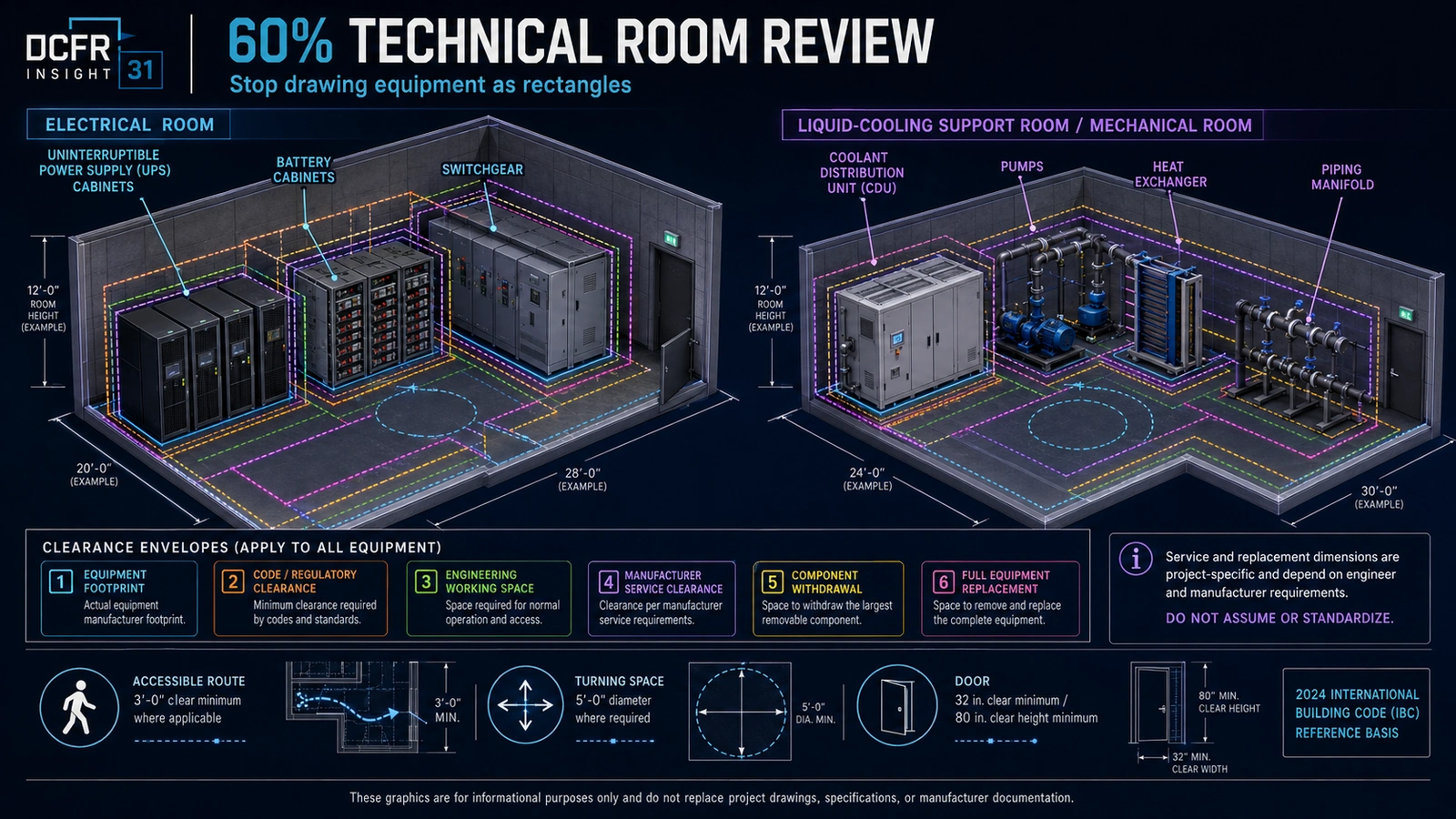
Each major item needs separate envelopes. These dimensions are not interchangeable. A room may fit installed equipment and still be impossible to maintain or replace.
- 1
1 — Equipment footprint
Actual installed equipment.
- 2
2 — Code / regulatory clearance
Only where applicable.
- 3
3 — Engineering working space
Established by the responsible design engineer and applicable requirements.
- 4
4 — Manufacturer service clearance
Doors, panels, filters, coils, breakers, pumps, and batteries.
- 5
5 — Component withdrawal
The largest removable component.
- 6
6 — Full-equipment replacement
Space and route for removing the complete equipment.
Final service, working, withdrawal, and replacement dimensions must come from applicable code, the responsible engineer, actual selected equipment, and approved manufacturer documentation. Infographic dimensions are illustrative, not universal technical requirements.
Doors — Code Compliance vs Equipment Replacement
CODE / REGULATORY — Under the 2024 International Building Code (IBC) Section 1010.1.1 reference basis, applicable means-of-egress doors generally require a 32-inch minimum clear opening width and 80-inch minimum clear opening height. Verify the adopted edition, local amendments, occupancy conditions, and applicable exceptions. A 32-inch clear egress width does not equal an adequate equipment replacement opening. MANUFACTURER / ENGINEERING / PROJECT-SPECIFIC CONFIRMATION REQUIRED — verify shipping width and height, disassembly, rigging, turning geometry, adjacent equipment, removable panels, and floor loading for Uninterruptible Power Supply (UPS) equipment, switchgear, battery cabinets, Coolant Distribution Units (CDUs), pumps, heat exchangers, and transformers.
Accessibility — Apply It Correctly
CODE / REGULATORY — Where an accessible route is required, the Americans with Disabilities Act (ADA) Accessibility Standards generally use a 36-inch minimum clear walking surface, with limited conditions permitting shorter 32-inch clear segments. Confirm applicability and project conditions. Do not imply every technical equipment aisle is an accessible route. Distinguish accessible circulation, employee work area, equipment access, electrical working space, manufacturer service clearance, egress, and replacement path. Avoid both under-dimensioning and blind use of one dimension everywhere.
At 60%, Review the Roof Like a Technical Floor Plan
A roof with every unit fitting in plan can still fail operationally if equipment cannot be serviced, replaced, or reroofed around.
Roof Interface Review
| Roof Interface | Owner-Side Check |
|---|---|
| Equipment curbs | Location, size, structural support |
| Roof penetrations | Quantity, grouping, waterproofing |
| Primary drainage | Coordination with equipment and structure |
| Overflow drainage | Unobstructed |
| Walkways | Maintenance route |
| Screens | Wind / structure / acoustics |
| Exhaust | Separation / re-entrainment |
| Louvers / intakes | Airflow / weather |
| Lightning protection | Equipment coordination |
| Fall protection | Maintenance safety |
| Replacement | Crane / rigging access |
| Future equipment | Reserved zones |
At 60%, Review Penetration Strategy
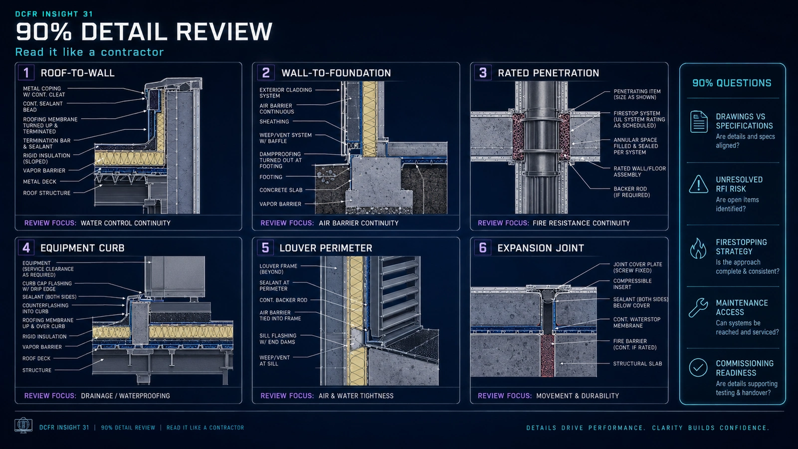
Ask whether every assembly maintains water, air, thermal, vapor, fire-resistance, acoustic, and security control when systems pass through it. Review roof-to-wall, wall-to-foundation, rated-wall, cable-tray, busway and pipe penetrations, louvers, equipment curbs, and expansion joints.
Require an Equipment Replacement-Path Drawing
Trace public road → secured entry → internal service road → laydown → crane or forklift zone → removable panel or door → internal route → technical room → final position. Record the largest shipping section, width, height, weight, turning requirement, opening, floor loading, rigging, temporary protection, and shutdown consequence. MANUFACTURER / ENGINEERING / PROJECT-SPECIFIC CONFIRMATION REQUIRED.
A FACILITY DESIGNED TO OPERATE FOR DECADES SHOULD NOT REQUIRE MAJOR DEMOLITION EVERY TIME A CRITICAL ASSET REACHES END OF LIFE.
60% Owner-Side Release Gate
Release only when technical-room geometry, service envelopes, replacement paths, openings, penetrations, rated walls, roof, structure, distribution, security, vendor data, and procurement dependencies are coordinated or explicitly logged.
60% Owner-Side Release Gate
| Review Item | Required Status |
|---|---|
| Technical-room dimensions | Coordinated |
| Equipment service envelopes | Shown |
| Major replacement paths | Demonstrated |
| Door/opening sizes | Verified |
| Major penetrations | Coordinated |
| Rated walls | Coordinated with systems |
| Roof curbs | Located |
| Drainage | Coordinated |
| Louvers | Sized / located |
| Structural openings | Coordinated |
| Equipment pads | Coordinated |
| Cable / tray / busway zones | Coordinated |
| Mechanical distribution | Coordinated |
| Fire-protection interfaces | Coordinated |
| Security interfaces | Coordinated |
| Vendor information | Incorporated or logged |
| Major procurement dependencies | Identified |
90% Review — Read It Like a Contractor
If this package were bid and built tomorrow, what would become a Request for Information, submittal exception, change order, field conflict, water-intrusion problem, commissioning failure, maintenance problem, or operational-shutdown risk? This review should be forensic.
Review Drawings and Specifications Together
Cross-check wall type ↔ specification; roof assembly ↔ roofing specification; door rating ↔ schedule ↔ hardware; firestop ↔ penetration detail ↔ specification; sealant ↔ joint detail; insulation ↔ performance criteria; louver ↔ performance specification; equipment pad ↔ structural requirement; finish ↔ room use; and access panel ↔ maintainable component. The contractor should not discover contradictions first.
90% Envelope Review — Focus on Transitions
Review roof-to-wall, wall-to-foundation, parapet, door threshold, louver perimeter, pipe and cable penetrations, equipment curbs, expansion joints, and screen attachments. Trace WATER CONTROL, AIR CONTROL, THERMAL CONTROL, VAPOR CONTROL, and FIRE RESISTANCE continuously through every interface.
Firestopping Is a System — Not a Generic Note
Do not accept “Firestop all penetrations” as complete coordination. Understand the rated assembly, penetrating item and size, opening, annular space, tested/listed firestop system, backing or packing, inspection, and identification. Selection and approval of the actual tested/listed system is project-specific and requires responsible design, firestop, and inspection coordination.
Review Maintenance Above Ceilings and Behind Equipment
Can each valve, filter, breaker, panel, actuator, detector, leak sensor, fire damper, pump seal, and removable pipe section be accessed and serviced? Can one redundant system be maintained while the other remains available? Building Information Modeling (BIM) clash detection is not enough. “Zero clashes” does not prove operational maintainability.
Long-Lead Decisions Must Be Visible
Design and procurement milestones do not always coincide. Critical packages include transformers, switchgear, generators, UPS equipment, batteries, chillers, CDUs, air-handling equipment, modular electrical and mechanical skids, and façade systems. Lead times are market-, manufacturer-, configuration-, project-, and date-specific; require current quotations and schedules. Need-on-site date ← transport and installation ← factory testing ← manufacturing ← approved submittal ← purchase order ← design release ← owner decision.
Procurement Dependency Register
Make every design decision, vendor-data dependency, required release, and late impact visible. Required release dates are PROJECT-SPECIFIC CONFIRMATION REQUIRED.
Procurement Dependency Register
| Package | Design Decision Required | Vendor Data Needed | Required Release | Design Impact if Late |
|---|---|---|---|---|
| Transformer | Rating / configuration | Dimensions, weight, connections | Project-specific | Yard / structure / utility |
| Switchgear | Topology | Lineup dimensions | Project-specific | Room / openings / busway |
| Generator | Unit / model | Dimensions, weight, exhaust | Project-specific | Yard / acoustics / fuel |
| UPS | Architecture | Cabinet geometry | Project-specific | Room / battery / access |
| Battery | Chemistry / configuration | Cabinet / rack data | Project-specific | Fire / mechanical / room |
| CDU | Cooling architecture | Capacity / connections | Project-specific | Piping / drainage / access |
| Chiller | Equipment selection | Dimensions / loads | Project-specific | Structure / yard / roof |
Lead times and releases require current, project-specific quotations and schedules.
90% Release Gate
Close or explicitly track code and authority comments, deviations, equipment geometry and replacement routes, rated assemblies, firestop, envelope transitions, roof and drainage, drawing/specification coordination, long-lead release bases, commissioning and maintenance access, vendor items, and owner decisions.
90% Release Gate
| Review Item | Required Status |
|---|---|
| Major code comments | Closed |
| Authority comments | Closed / tracked |
| Reference-design deviations | Approved |
| Major equipment dimensions | Incorporated |
| Equipment replacement routes | Verified |
| Rated assemblies | Detailed |
| Major firestop conditions | Coordinated |
| Envelope transitions | Detailed |
| Roof penetrations | Coordinated |
| Drainage | Coordinated |
| Specifications | Coordinated with drawings |
| Long-lead packages | Release basis established |
| Commissioning access | Verified |
| Maintenance access | Verified |
| Open vendor items | Explicitly logged |
| Owner decisions | Closed or escalated |
Issued-for-Construction — Control Remaining Uncertainty
A construction release does not mean every unknown has disappeared. It means remaining unknowns are explicit and controlled. Register authority conditions, deferred submittals, vendor and utility dependencies, field verification, owner-furnished equipment, temporary works, mockups, preinstallation meetings, commissioning dependencies, and future phases. Each needs an owner, due date, affected construction activity, last responsible decision date, and closure evidence.
Write Better Owner Review Comments
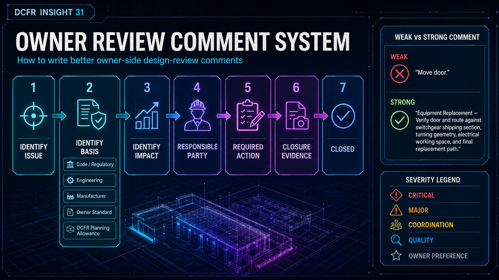
WEAK — Move door. STRONG — EQUIPMENT REPLACEMENT: Current door location conflicts with the documented switchgear replacement route. Architect and electrical Engineer of Record (EOR) to verify largest shipping section, turning geometry, electrical working space, egress, and final route before the next issue. WEAK — Corridor too narrow. STRONG — ACCESS / MAINTAINABILITY: Confirm whether this route serves accessible circulation, routine maintenance, component withdrawal, or complete replacement. Dimension the controlling clear width and identify whether the basis is code/regulatory, engineering, manufacturer, owner standard, or planning allowance. WEAK — Coordinate with mechanical. STRONG — RATED PENETRATION: Mechanical piping crosses the rated enclosure. Architect, mechanical Engineer of Record, and fire-protection team to coordinate opening, penetrant configuration, rated-assembly continuity, and applicable tested/listed firestop system before release.
Owner Review Comment System
A useful comment moves to objective closure.
- 1
1 — Identify issue
What is the risk or conflict?
- 2
2 — Identify basis
Code/regulatory, engineering, manufacturer, owner standard, or planning allowance?
- 3
3 — Identify impact
Capacity, safety, cost, schedule, operations, or commissioning?
- 4
4 — Responsible party
Who must resolve it?
- 5
5 — Required action
What must change, be documented, or be confirmed?
- 6
6 — Closure evidence
How will resolution be verified?
- 7
7 — Closed
Issue resolved and documented.
Comment Severity
Do not let cosmetic markup volume hide critical technical risk.
Comment Severity
| Severity | Meaning | Example |
|---|---|---|
| CRITICAL | Prevents safe or responsible release. | Life safety, insufficient capacity, unresolved utility conflict. |
| MAJOR | Material cost, schedule, or operational impact. | Equipment replacement blocked. |
| COORDINATION | Multidiscipline resolution required. | Pipe through rated wall. |
| QUALITY | Documentation incomplete. | Missing detail reference. |
| OWNER PREFERENCE | Desirable but not governing. | Noncritical finish preference. |
Every Comment Needs Closure Evidence
Do not close a comment because someone writes “Addressed.” Evidence may be a revised drawing/detail reference, approved vendor dimension, engineer confirmation, Authority Having Jurisdiction (AHJ) response, replacement-route drawing, owner decision, deviation record, or tested/listed system identification.
Owner-Side Design Review Dashboard
Comment count is not project risk. Five unresolved critical decisions may matter more than hundreds of drafting comments.
Owner-Side Design Review Dashboard
| Metric | Why It Matters |
|---|---|
| Critical comments open | Release risk |
| Major comments open | Cost / schedule risk |
| Decisions overdue | Design latency |
| Authority issues open | Permit risk |
| Vendor dependencies open | Procurement risk |
| Reference-design deviations open | Portfolio-control risk |
| Equipment clearances unverified | Constructability / operations risk |
| Replacement paths unverified | Lifecycle risk |
| Commissioning dependencies open | Turnover risk |
| Repeat comments from prior milestone | Closure-quality problem |
The Owner-Side Review Sequence
REVIEW THE SITE BEFORE THE ROOMS. REVIEW THE ROOMS BEFORE THE DETAILS. REVIEW THE INTERFACES BEFORE THE FINISHES. REVIEW REPLACEMENT BEFORE APPEARANCE. REVIEW COMMISSIONING BEFORE CONSTRUCTION HIDES ACCESS. REVIEW UNRESOLVED DECISIONS BEFORE RELEASING MORE DOCUMENTS.
Common Owner-Side Review Failures
Each failure allows unresolved risk to migrate downstream.
- 1
FAILURE 1
Reviewing every milestone with the same checklist.
- 2
FAILURE 2
Reviewing only architectural drawings.
- 3
FAILURE 3
Assuming Building Information Modeling clash detection proves maintainability.
- 4
FAILURE 4
Reviewing equipment after room geometry has been frozen.
- 5
FAILURE 5
Tracking comments without decision ownership.
- 6
FAILURE 6
Closing comments without objective evidence.
- 7
FAILURE 7
Ignoring specifications.
- 8
FAILURE 8
Ignoring commissioning requirements.
- 9
FAILURE 9
Ignoring full-equipment replacement.
- 10
FAILURE 10
Issuing documents with hidden assumptions.
The DCFR Design Principle
30%: PROVE THE ARCHITECTURE. 60%: PROVE THE INTERFACES. 90%: PROVE CONSTRUCTION READINESS. ISSUED-FOR-CONSTRUCTION: CONTROL EVERY REMAINING UNCERTAINTY.
A DESIGN PACKAGE SHOULD ADVANCE ONLY WHEN THE DECISIONS APPROPRIATE TO THAT STAGE ARE SUFFICIENTLY RESOLVED TO MAKE THE NEXT STAGE SAFE.
Final Takeaway
For an owner-side architect, the objective is not to produce the most redlines. It is to identify the few unresolved decisions and interfaces that materially affect capacity, permitting, procurement, construction, commissioning, maintainability, replacement, cost, schedule, and operational continuity—and force them to closure before they migrate downstream.
30%, 60%, AND 90% SHOULD NOT DESCRIBE HOW MUCH HAS BEEN DRAWN. THEY SHOULD DESCRIBE HOW MUCH CRITICAL DESIGN RISK HAS BEEN RESOLVED.
Current Technical Basis — August 2026
International Code Council
2024 International Building CodeModel-code reference basis; verify adopted edition, amendments, occupancy conditions, and exceptions.
International Code Council
2024 International Fire CodeModel-code reference basis; verify adopted edition, amendments, fire-code official requirements, and project conditions.
United States Access Board
Americans with Disabilities Act Accessibility StandardsVerify scope, applicable route conditions, and project-specific requirements.
National Fire Protection Association (NFPA)
National Electrical CodeVerify the adopted edition and engineering application for the project.
National Fire Protection Association
Codes and StandardsIdentify and verify project-applicable fire-protection standards with responsible professionals and authorities.
Project-specific equipment manufacturers
Approved Product Installation, Service, and Replacement DocumentationActual equipment clearances, shipping sections, service envelopes, and replacement requirements must come from approved selected-equipment documentation.
Technical basis reviewed August 2026. Cooling technology, equipment capability, vendor qualification, and industry guidance continue to evolve; project decisions should use the latest applicable manufacturer data and professional engineering analysis.
Capacity-delivery review checklist
What to verify before the next release gate.
- Review the site before rooms, rooms before details, and interfaces before finishes.
- Verify capacity, service envelopes, full-equipment replacement, authority conditions, procurement dependencies, and commissioning access.
- Assign every unresolved decision an owner, deadline, downstream impact, and objective closure evidence.
What DCFR would flag
Delivery risks that should be visible early.
DCFR would flag target capacity unreconciled with geometry; missing equipment data; undimensioned fire access; absent service or replacement envelopes; personnel egress treated as equipment replacement; unproven replacement routes; unresolved rated penetrations; generic roof or envelope transitions; drawing/specification conflicts; hidden vendor dependencies; open authority issues; procurement dependent on undecided design; missing commissioning access; or critical comments repeatedly carried forward.
Professional confirmation required
Items requiring project-specific validation.
PROJECT-SPECIFIC CONFIRMATION REQUIRED for adopted codes and amendments, authority interpretations, insurer criteria, local setbacks, actual equipment geometry and clearances, engineering working space, accessibility scope, tested/listed firestop systems, procurement lead times, vendor release dates, commissioning requirements, and every early planning allowance.
Final takeaway
30%, 60%, AND 90% SHOULD NOT DESCRIBE HOW MUCH HAS BEEN DRAWN. THEY SHOULD DESCRIBE HOW MUCH CRITICAL DESIGN RISK HAS BEEN RESOLVED.
Surface site, code, utility, and delivery risk before it becomes expensive.
DCFR converts early assumptions into planning-grade flags, confirmation registers, and decision-ready feasibility outputs.