
DCFR Insight 32 / Data Center Architecture + Operations
Data Center Technical Rooms: Clearances, Cooling, and Equipment Replacement
An owner-side architectural guide to electrical, Uninterruptible Power Supply (UPS), battery, Computer Room Air Handler (CRAH), liquid-cooling, and pump rooms—covering service clearances, component withdrawal, leak management, maintainability, and full equipment replacement.
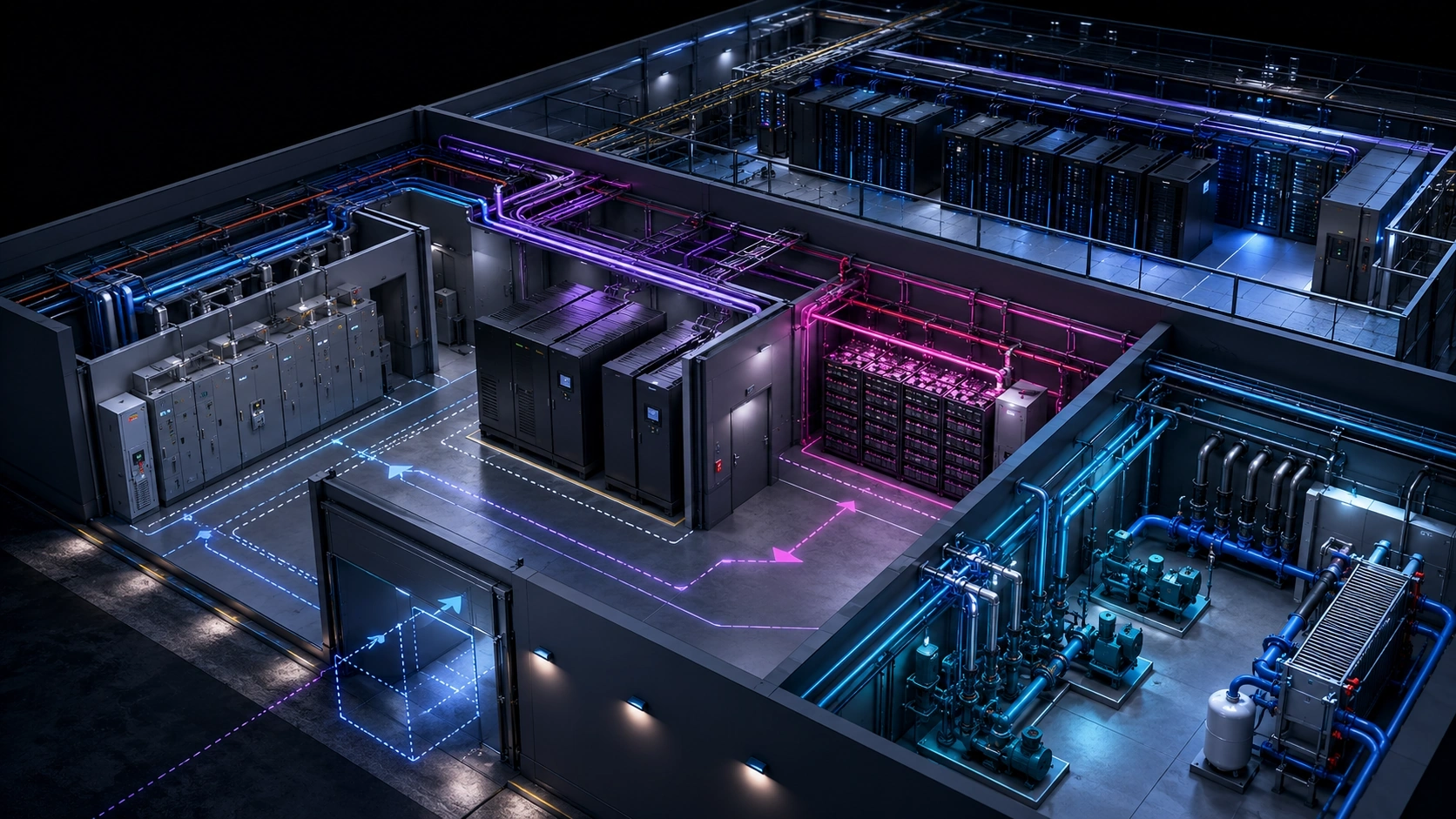
Technical Room Types Overview
Technical rooms are active operational infrastructure, not leftover space and not a generic “MEP room.” The six primary categories are Electrical / Switchgear; Uninterruptible Power Supply; Battery / Energy Storage; Chilled-Water / Computer Room Air Handler; Liquid-Cooling / Coolant Distribution Unit (CDU); and Pump / Heat Exchanger. Each has different regulatory and engineering requirements, equipment interfaces, service conditions, fire-protection conditions, maintenance activities, and replacement requirements. Owner-side architecture must coordinate those differences before walls, doors, structure, overhead distribution, and adjacent circulation are released. The project basis may involve the International Building Code (IBC), International Fire Code (IFC), National Electrical Code (NEC), applicable National Fire Protection Association (NFPA) standards, and Americans with Disabilities Act (ADA) requirements. Applicability comes from adopted editions, local amendments, actual systems, and review by the Authority Having Jurisdiction (AHJ)—not from a generic room label.
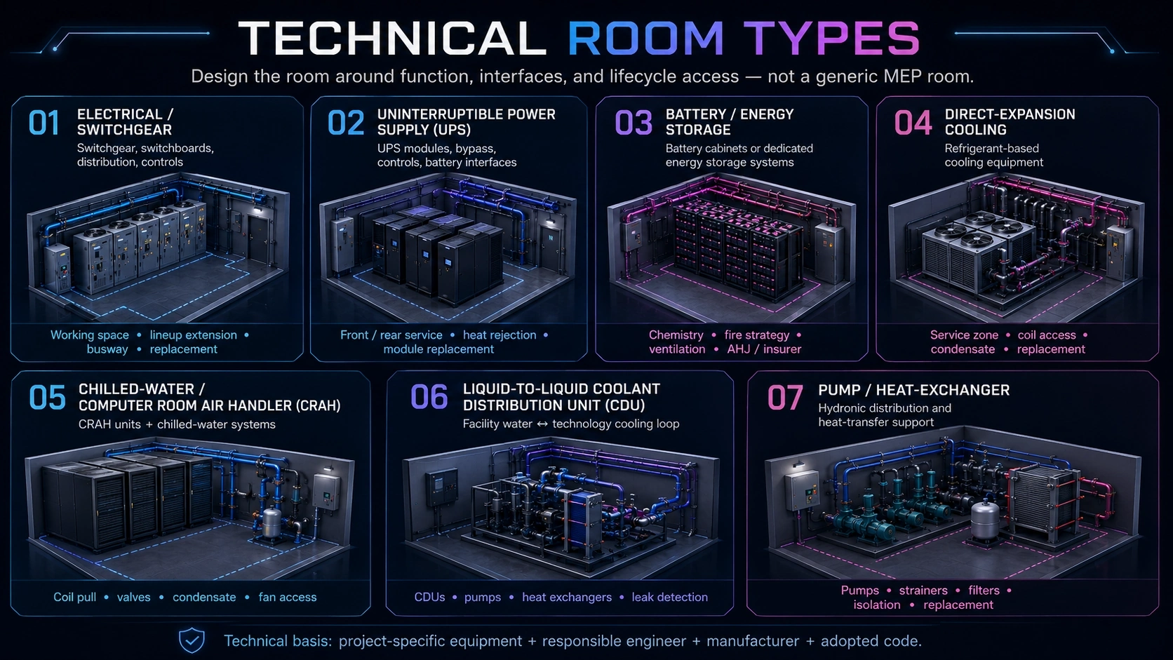
The Six Clearance Envelopes
A coordinated plan overlays six different envelopes. Each answers a different question and carries a stated controlling basis.
01 — Equipment footprint
MANUFACTURER / ENGINEERING: Installed dimensions, anchorage, connections, and lineup geometry for the selected equipment.
02 — Code / regulatory clearance
CODE / REGULATORY: Applicable electrical working space, egress, life-safety circulation, accessible-route width where required, and door operation based on actual conditions.
03 — Engineering working space
ENGINEERING: Space to operate, isolate, test, and work safely on the configured system, confirmed by the responsible Engineer of Record (EOR).
04 — Manufacturer service clearance
MANUFACTURER: Required service faces, open panels, technician positions, tools, and maintenance carts.
05 — Component withdrawal envelope
MANUFACTURER / ENGINEERING: Swept path and laydown for the largest breaker, module, fan, motor, coil, filter, or heat-exchanger component.
06 — Full equipment replacement envelope
PROJECT-SPECIFIC CONFIRMATION REQUIRED: Movement of the full unit or largest shipping section from its installed position to the truck or crane. Owner standards may add requirements but do not replace the project test.
DCFR PLANNING ALLOWANCE is not code. DO NOT USE “3'-0" CLEAR TYP.” UNLESS THE CONTROLLING BASIS FOR THAT DIMENSION IS KNOWN.
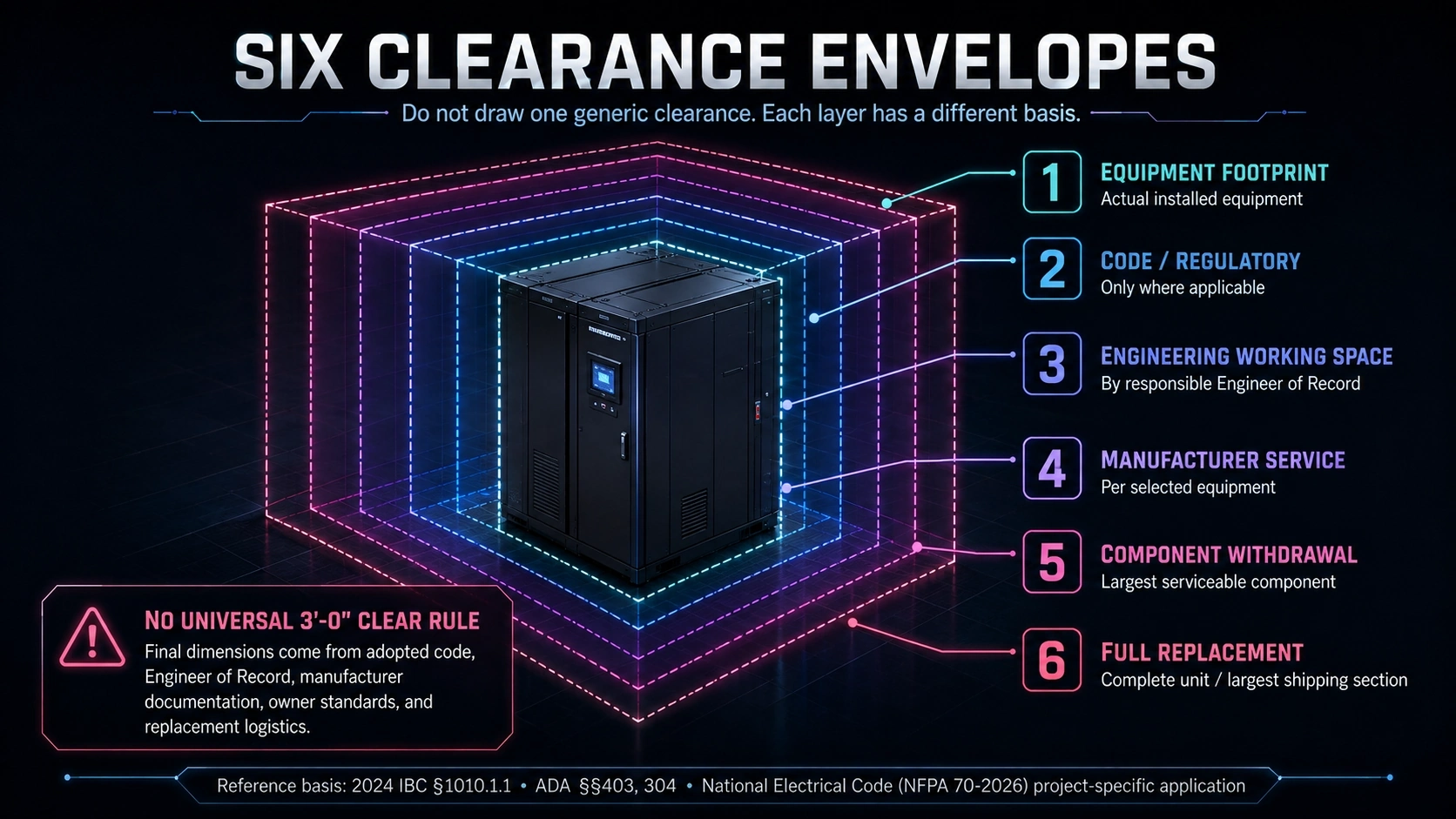
Electrical / Switchgear Room — Technical Explanation
Switchgear, switchboards, distribution equipment, protective devices, controls, and metering form a coordinated lineup rather than isolated rectangles. Cable tray and busway interfaces must reach the correct zones without blocking equipment doors, panels, lifting, or a protected lineup extension. The architect should model doors and panels in their operating positions, identify shipping sections and handling methods, and coordinate floor loading, egress, rated construction, rigging, and the route for complete replacement. Installation access does not prove that an energized facility can later remove the same lineup. There is no universal electrical working-space depth. CODE / REGULATORY + ENGINEERING: Final working space depends on the adopted NEC, voltage, equipment configuration, condition, listing, and confirmation by the electrical EOR.
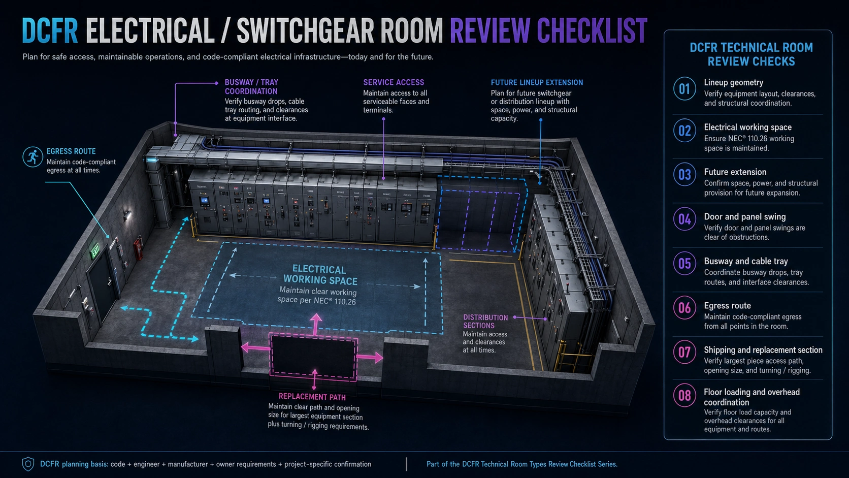
Electrical / Switchgear — Owner-Side Review Questions
Resolve each question against the actual lineup and coordinated building model.
Has the actual equipment lineup been received?
Verify and document before design release.
Has the electrical Engineer of Record confirmed required working space?
Verify and document before design release.
Is future lineup extension protected?
Verify and document before design release.
Can all equipment doors and panels fully open?
Verify and document before design release.
Are busway and cable-tray interfaces coordinated?
Verify and document before design release.
Is required egress maintained?
Verify and document before design release.
What is the largest shipping section?
Verify and document before design release.
Can complete equipment replacement occur without demolition?
Verify and document before design release.
Is floor loading confirmed?
Verify and document before design release.
Is lifting / rigging practical?
Verify and document before design release.
Uninterruptible Power Supply Room — Technical Explanation
A UPS room combines UPS modules, static bypass, maintenance bypass, input/output interfaces, battery interfaces, controls, and cooling. The approved operating basis—not a presumed universal topology—determines how redundancy must perform during planned service. ROUTINE SERVICE preserves service faces, cabinet-door operation, controls, tools, and safe front or rear technician access. COMPONENT / MODULE WITHDRAWAL adds the power-module pull, handling cart, swept path, and laydown area. MANUFACTURER requirements control these service and withdrawal zones. COMPLETE EQUIPMENT REPLACEMENT tests the cabinet or largest shipping section through every opening and turn, with a project-specific handling method, structural capacity, and shutdown plan. These three operations are not interchangeable.
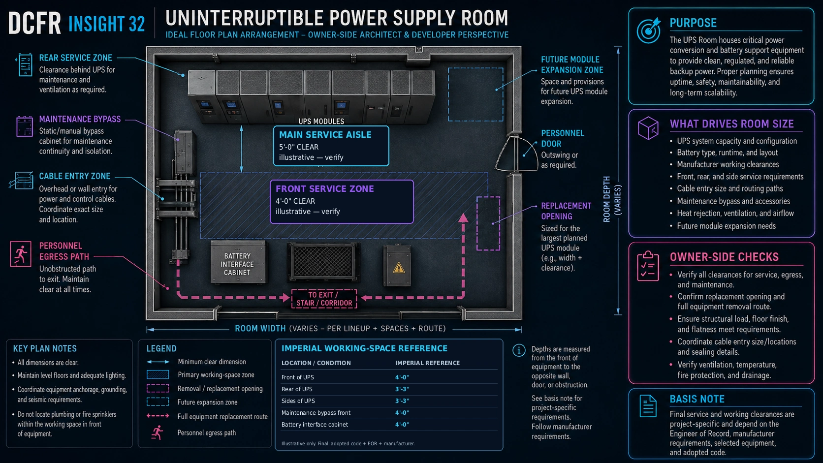
Uninterruptible Power Supply — Owner-Side Review Questions
Verify the selected equipment and approved operating strategy before release.
Are manufacturer service faces confirmed?
Verify and document before design release.
Can all power modules be withdrawn?
Verify and document before design release.
Is maintenance bypass accessible?
Verify and document before design release.
Are electrical working spaces confirmed?
Verify and document before design release.
Is heat rejection / cooling coordinated?
Verify and document before design release.
Is the battery interface coordinated?
Verify and document before design release.
Can the largest shipping section reach and leave the room?
Verify and document before design release.
Can the intended redundancy strategy be maintained during service where required?
Verify and document before design release.
Battery / Energy Storage Room — Technical Explanation
Battery-room design depends on the actual technology: chemistry, capacity, configuration, battery cabinets or racks, and whether the equipment is part of a Battery Energy Storage System (BESS). There is no universal battery spacing or separation value. CODE / REGULATORY + ENGINEERING + MANUFACTURER: Coordinate thermal management, ventilation, detection, fire protection, emergency isolation and response, listing conditions, insurer criteria, AHJ review, and cabinet or module replacement. The applicable strategy changes with the selected technology and adopted requirements; architecture must track the decisions rather than assume them.
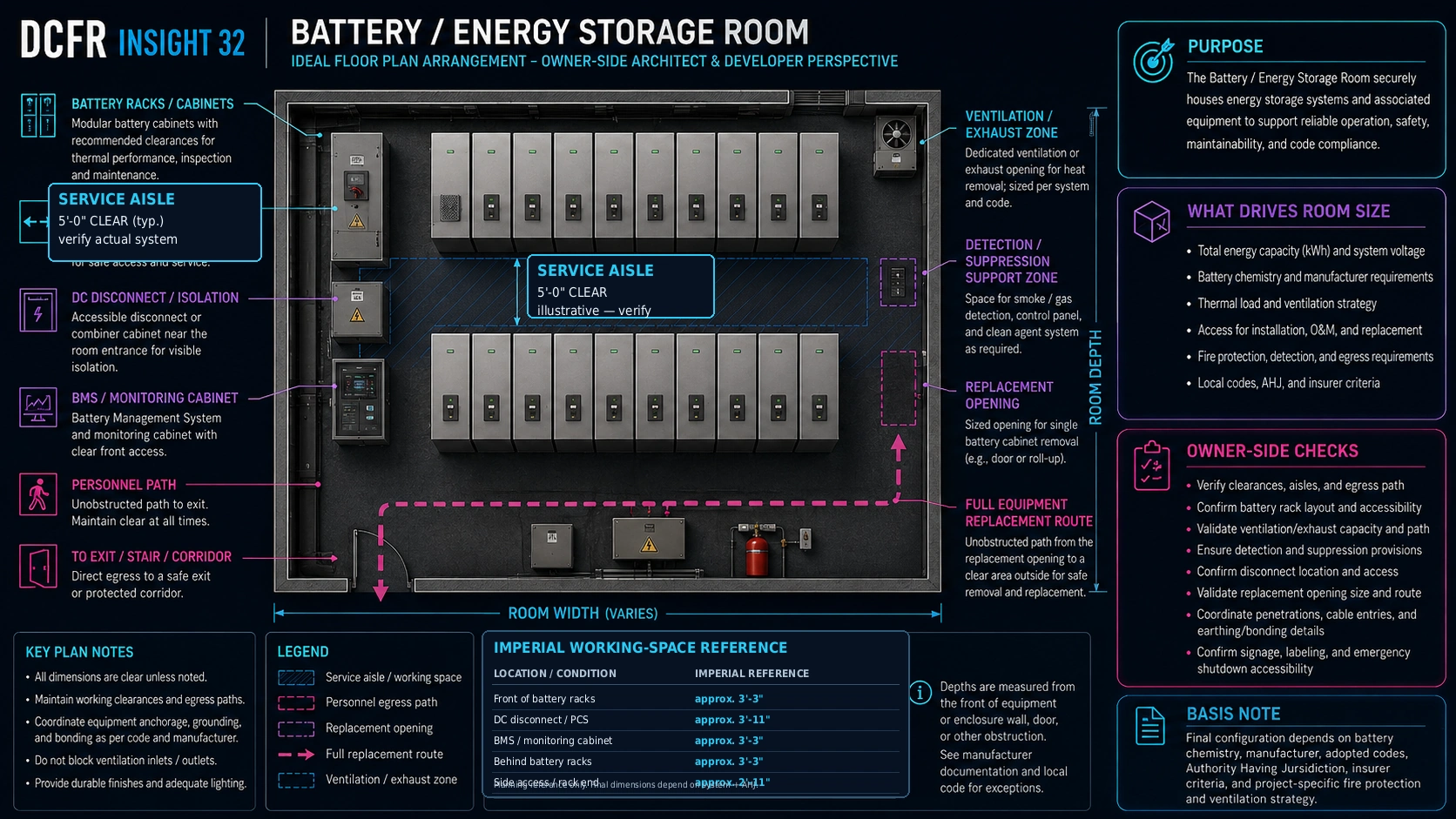
Battery / Energy Storage — Owner-Side Review Questions
Close technology, protection, response, and replacement decisions together.
Is battery chemistry confirmed?
Verify and document before design release.
Is system capacity/configuration confirmed?
Verify and document before design release.
Are manufacturer service clearances identified?
Verify and document before design release.
Is fire detection coordinated?
Verify and document before design release.
Is fire protection coordinated?
Verify and document before design release.
Is ventilation / thermal management confirmed?
Verify and document before design release.
Is emergency isolation defined?
Verify and document before design release.
Can modules/cabinets be replaced?
Verify and document before design release.
Are insurer requirements tracked?
Verify and document before design release.
Are Authority Having Jurisdiction requirements tracked?
Verify and document before design release.
Chilled-Water / Computer Room Air Handler Room — Technical Explanation
A chilled-water CRAH room coordinates chilled-water supply and return, valves, strainers, filters, fans, coils, controls, condensate, and drainage around the selected unit. Pipework and overhead trays that look coordinated in plan can obstruct access when a filter, fan, or coil moves through its full removal path. MANUFACTURER: Coil-pull and component-withdrawal requirements can control room geometry. Draw the three-dimensional extraction path and laydown area, then keep walls, columns, risers, piping, cable tray, and unrelated equipment out of it. Full-unit replacement and required egress remain separate tests.
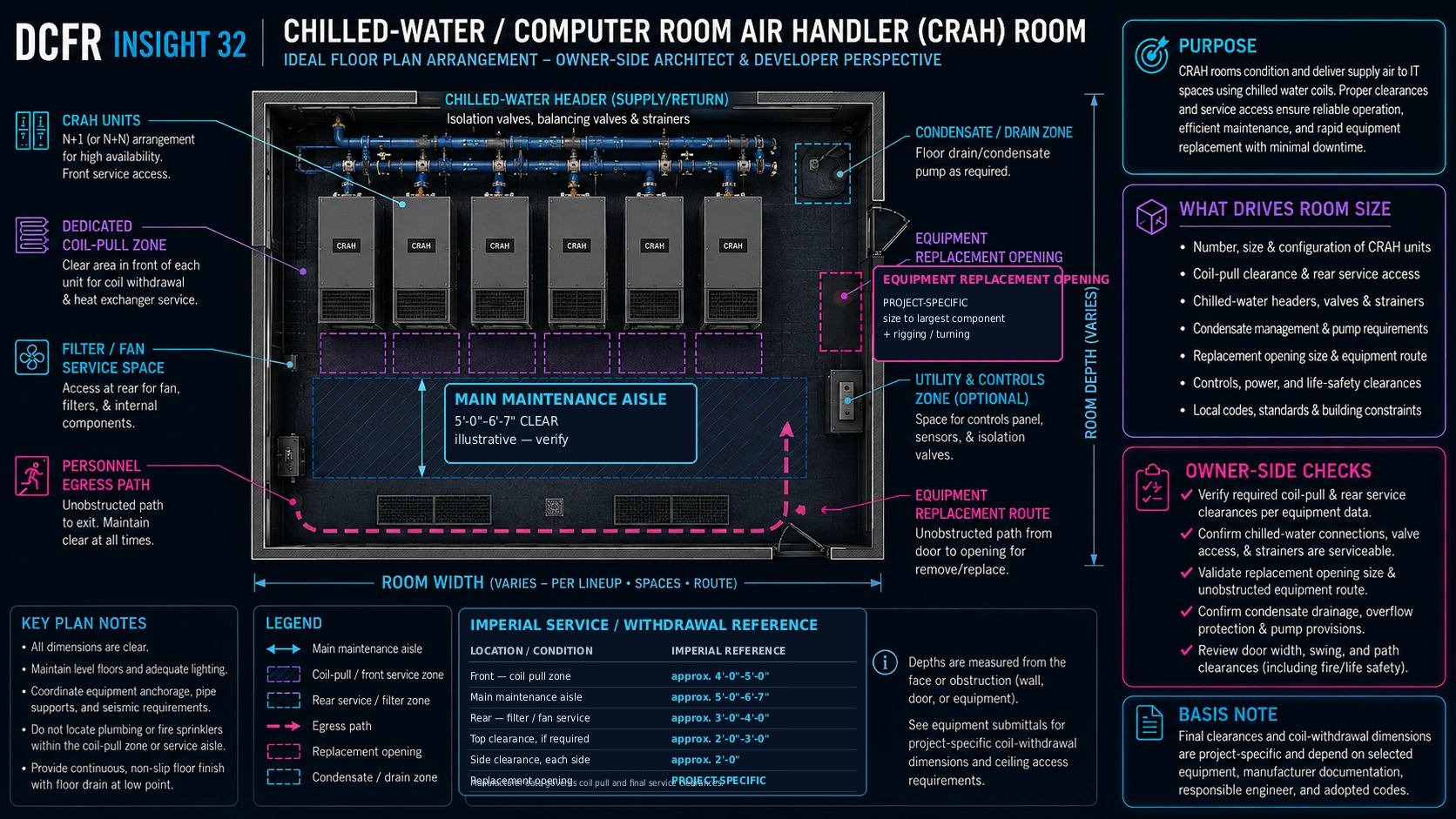
Chilled-Water / Computer Room Air Handler — Owner-Side Review Questions
Test component work and full-unit movement independently.
Is manufacturer coil-pull clearance known?
Verify and document before design release.
Can filters be replaced?
Verify and document before design release.
Can fans and internal assemblies be removed?
Verify and document before design release.
Are valves and strainers accessible?
Verify and document before design release.
Is condensate / drainage coordinated?
Verify and document before design release.
Are overhead pipes and trays outside service zones?
Verify and document before design release.
Can the full Computer Room Air Handler unit be replaced?
Verify and document before design release.
Does replacement preserve required egress?
Verify and document before design release.
Liquid-Cooling / Coolant Distribution Unit Room — Technical Explanation
The FACILITY COOLING SYSTEM rejects and transports heat at the building-infrastructure level. The TECHNOLOGY COOLING LOOP serves Information Technology (IT) equipment, including approved Artificial Intelligence (AI) deployments, under its own fluid-quality, temperature, pressure, flow, and reliability requirements. CDUs transfer heat and control conditions across the engineered interface. The room must integrate Coolant Distribution Units, supply and return headers, pumps, heat exchangers, strainers, filters, isolation valves, controls, leak detection, drainage, containment, redundancy, and protected future capacity. System boundaries and redundancy follow the approved engineering and owner basis; no topology is universal. MANUFACTURER service zones govern selected equipment. The REPLACEMENT OPENING is PROJECT-SPECIFIC: determine it from the largest shipping section, disassembly strategy, rigging equipment, turning geometry, structural opening, access route, and replacement procedure. Do not substitute a universal opening dimension.
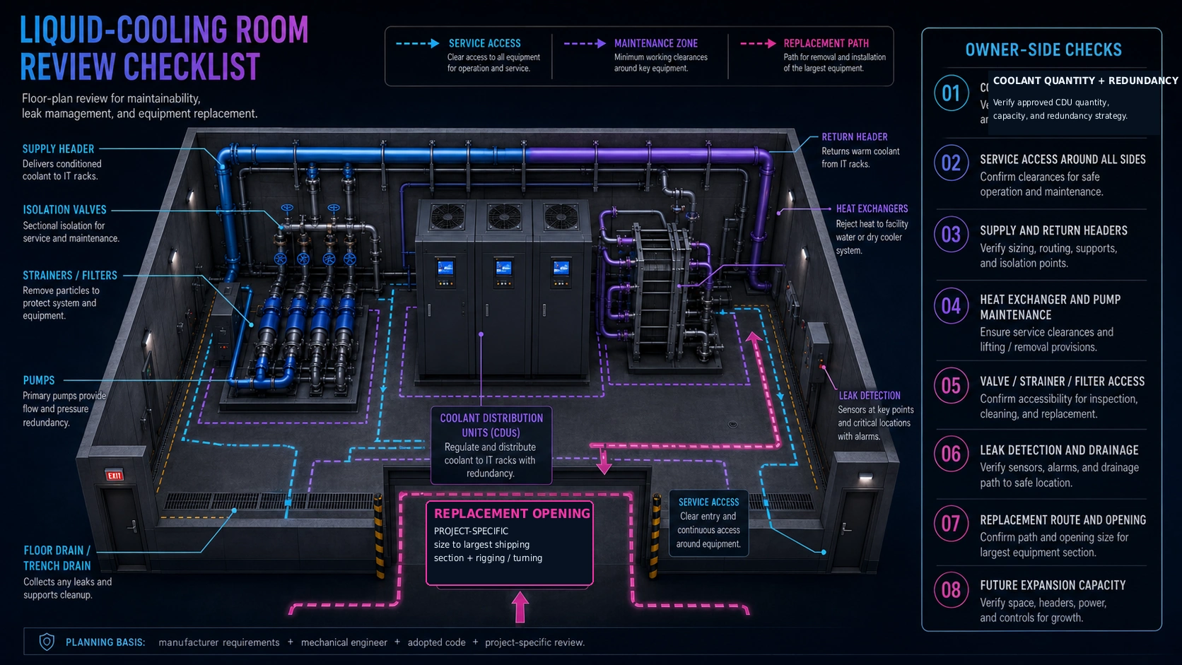
Liquid-Cooling / Coolant Distribution Unit — Owner-Side Review Questions
Verify both cooling loops, their interface, and lifecycle access as one coordinated system.
How many Coolant Distribution Units are required?
Verify and document before design release.
What redundancy philosophy is approved?
Verify and document before design release.
What manufacturer service zones apply?
Verify and document before design release.
Can pumps be removed?
Verify and document before design release.
Can heat exchangers be serviced?
Verify and document before design release.
Can filters and strainers be opened?
Verify and document before design release.
Are isolation valves accessible?
Verify and document before design release.
How are leaks detected?
Verify and document before design release.
Where does leaked coolant drain?
Verify and document before design release.
Is secondary containment required?
Verify and document before design release.
Can the largest Coolant Distribution Unit or component leave the room?
Verify and document before design release.
Is future expansion capacity protected?
Verify and document before design release.
Pump / Heat-Exchanger Room — Technical Explanation
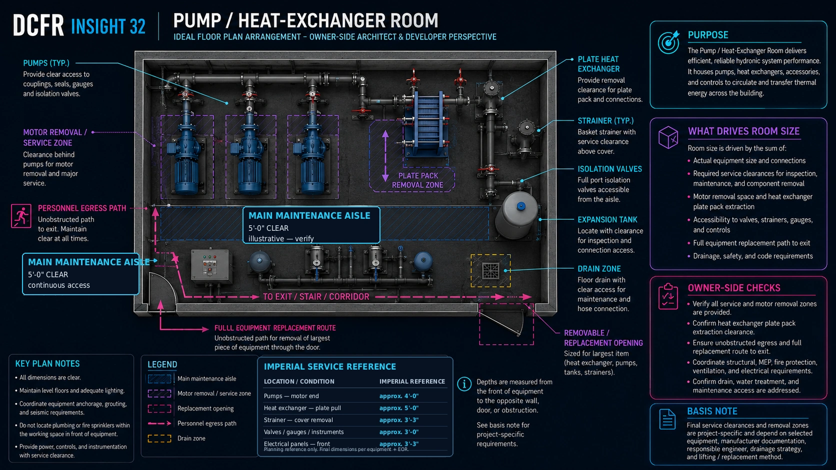
Primary pumps, secondary pumps, motors, heat exchangers, strainers, filters, isolation valves, treatment equipment, controls, and drains create overlapping operating and maintenance zones. A clear walking aisle does not prove that a motor can withdraw, a strainer can open, or heat-exchanger components can reach a laydown position. MANUFACTURER / ENGINEERING: Draw the largest withdrawal operation in plan and section. Coordinate reachable isolation, drains, lifting points and capacity, rigging travel, floor loading, spill response, replacement, and the operational consequence of taking equipment out of service.
Pump / Heat-Exchanger — Owner-Side Review Questions
Demonstrate service, isolation, lifting, and replacement with the selected equipment.
Can pump motors be withdrawn?
Verify and document before design release.
Can complete pumps be replaced?
Verify and document before design release.
Can strainers be opened?
Verify and document before design release.
Can filters be removed?
Verify and document before design release.
Can heat-exchanger components be serviced?
Verify and document before design release.
Are isolation valves reachable?
Verify and document before design release.
Is lifting / rigging practical?
Verify and document before design release.
Is drainage adequate?
Verify and document before design release.
Can equipment be isolated without unacceptable operational interruption?
Verify and document before design release.
Is complete replacement demonstrated?
Verify and document before design release.
Full Equipment Replacement Route
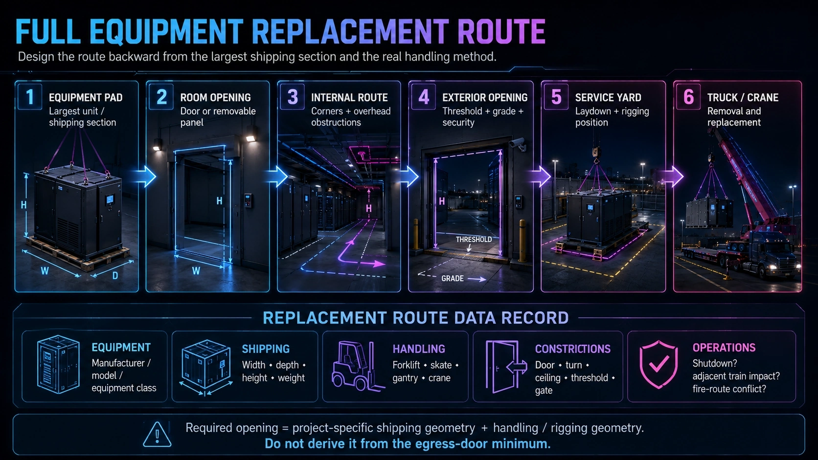
DAILY ACCESS IS NOT REPLACEMENT ACCESS. Trace one continuous route: EQUIPMENT → ROOM OPENING → CORRIDOR / INTERNAL ROUTE → EXTERIOR OPENING → SECURED SERVICE YARD → TRUCK / CRANE. For each major item, record shipping width, shipping depth, shipping height, shipping weight, removable sections, handling method, turning geometry, structural loading, overhead obstruction, threshold, slope, gate opening, crane access, and shutdown consequence. Any project dimensions must be recorded in feet-and-inches architectural notation. MANUFACTURER establishes shipping data. ENGINEERING confirms structure and handling. OWNER STANDARD establishes operational expectations. Openings, turns, route geometry, and replacement procedures require PROJECT-SPECIFIC CONFIRMATION.
Owner-Side Technical Room Release Gate
Before design release, record PASS or OPEN for every question. PASS requires documented evidence; an unresolved item remains OPEN rather than disappearing into a generic coordination note.
Owner-Side Technical Room Release Gate
| Question | Status |
|---|---|
| Actual equipment dimensions received? | PASS / OPEN |
| Engineering working spaces identified? | PASS / OPEN |
| Manufacturer service clearances shown? | PASS / OPEN |
| Component withdrawal demonstrated? | PASS / OPEN |
| Full equipment replacement demonstrated? | PASS / OPEN |
| Door / removable-panel opening verified? | PASS / OPEN |
| Turning / rigging geometry verified? | PASS / OPEN |
| Floor loading confirmed? | PASS / OPEN |
| Overhead coordination complete? | PASS / OPEN |
| Fire / rated construction coordinated? | PASS / OPEN |
| Drain / leak strategy coordinated? | PASS / OPEN |
| Commissioning access demonstrated? | PASS / OPEN |
| Future expansion protected? | PASS / OPEN |
A TECHNICAL ROOM IS NOT “90% COMPLETE” SIMPLY BECAUSE EVERY EQUIPMENT RECTANGLE APPEARS ON THE DRAWING.
Conclusion: Design the Lifecycle, Not the Rectangle
Owner-side architectural review makes equipment bases, clearance types, interfaces, and movement routes explicit before release. The goal is a room that supports safe operation, practical service, planned growth, and replacement throughout the asset life.
Early screening checklist
What to verify before advancing this site.
- Define each technical room by function and selected system architecture.
- Test all six clearance envelopes independently and label the controlling basis.
- Coordinate plan, section, structure, overhead systems, drainage, protection, commissioning, and operations.
- Prove component withdrawal, future expansion, and the complete change-out route before release.
What DCFR would flag
Risks surfaced at the screening stage.
DCFR would flag placeholder equipment; generic clearances with no stated basis; blocked service, withdrawal, or lifting zones; inaccessible valves and controls; unresolved battery or liquid-cooling hazards; overhead conflicts; or replacement that depends on demolition or interruption of unrelated critical systems.
Professional confirmation required
Items requiring licensed validation.
Planning guidance only. Verify adopted local code editions and amendments; confirm requirements with the AHJ, insurer, owner, responsible engineers, and manufacturers. Manufacturer requirements govern final service clearances. Project-specific engineering and code review are required.
Final takeaway
TECHNICAL ROOMS ARE OPERATIONAL INFRASTRUCTURE. DESIGN THEM FOR INSTALLATION, OPERATION, ISOLATION, INSPECTION, SERVICE, COMPONENT WITHDRAWAL, FULL REPLACEMENT, AND ADAPTATION—not simply to fit initial equipment.
Screen up to 20 candidate sites before selecting one for the full DCFR report.
Each DCFR Report Package includes a preliminary 20-site comparison PDF / export package plus one selected planning-grade feasibility report.