
DCFR Insight 101 / Reference Design Governance
From Prototype to Global Standard
How evidence gates turn one successful data center pilot into a controlled, repeatable reference design—without scaling hidden defects, undocumented workarounds, or site-specific assumptions.

A Pilot Proves One Outcome—A Standard Must Reproduce It
Data center programs often use prototype, pilot, standard design, and reference design as if they describe the same level of maturity. They do not. A prototype is a learning instrument. A pilot moves the solution into a real delivery environment. A reference design is a controlled body of design intent, interfaces, approved variants, acceptance tests, evidence, ownership, and change rules.
The distinction matters because replication magnifies both value and error. An ambiguity resolved by an experienced pilot team may become recurring field redesign when ten regional teams interpret it differently. A commissioning defect accepted under schedule pressure can become a portfolio-wide reliability exposure. A vendor substitution accepted without recording its assumptions can invalidate the performance basis of later sites.
The purpose of standardization is not to make every building identical. It is to make the engineering decisions repeatable, the local adaptations explicit, and the evidence traceable. A successful first project is therefore an input to the standard—not proof that a global standard already exists.
The Real Product Is a Decision System
The visible output is a coordinated package of drawings, specifications, schedules, models, details, and equipment requirements. The deeper product is the decision architecture beneath them: the performance intent, approved system topology, stable interfaces, bounded variants, acceptance logic, linked evidence, and governance rules that allow the package to be used again with confidence.
A mature reference design answers seven questions. What outcomes must every deployment achieve under normal, maintenance, and failure conditions? Which system arrangements establish the baseline? Where do disciplines, vendors, factory work, site work, utilities, and operator responsibilities meet? Which alternatives are pre-engineered? What test proves each critical requirement? Where is the supporting evidence? Who owns release, deviation, change, and rollback?
If one of those layers is absent, an organization may have a repeated layout, but it does not yet have a reliable reference design. Visual consistency is not technical repeatability, and a drawing library is not a governance system.
Prototype Build: Prove the Physical Hypothesis
The prototype should expose the highest-risk interfaces, not merely resemble the final building. Depending on the system, that may mean a full-scale power or cooling module, a representative data-hall bay, an envelope corner with roof and penetration conditions, or a combined factory-and-field assembly.
The build should test fabrication sequence, production hours, dimensional tolerances, tolerance accumulation, access for tools and inspection, safe work zones, transport restraints, lifting points, temporary stability, material substitutions, concealed conditions, trade stacking, connection sequence, and equipment replacement paths.
Work instructions are part of the test. If the assembly only succeeds because the designers stand beside the installers and answer undocumented questions, the prototype has exposed a knowledge gap. That gap must be resolved in the controlled package before replication.
Factory and System Test: Prove Controlled Performance
Factory acceptance testing should be derived from requirements, not assembled from a vendor's standard checklist after fabrication. Every critical requirement needs a defined operating state, test method, instrumentation plan, objective threshold, witness role, data record, failure disposition, and retest rule.
The test envelope should include partial load, design load, credible overload where appropriate, maintenance configurations, and selected failure states. It should exercise alarms, interlocks, permissives, control handoffs, loss and restoration of power or communications, leakage, thermal stability, vibration, pressure, water intrusion, and recovery behavior as applicable.
Verification and validation must remain distinct. Verification asks whether the product was built in accordance with the controlled technical definition. Validation asks whether the assembled solution satisfies the intended operational need. NASA's Systems Engineering Handbook describes this as proving that the product was built right and that the right product was built. It also recommends finding failures at the lowest practical level of integration, where correction creates less project impact.
 Open full-size plan ↗
Pilot Deployment: Prove the Delivery System
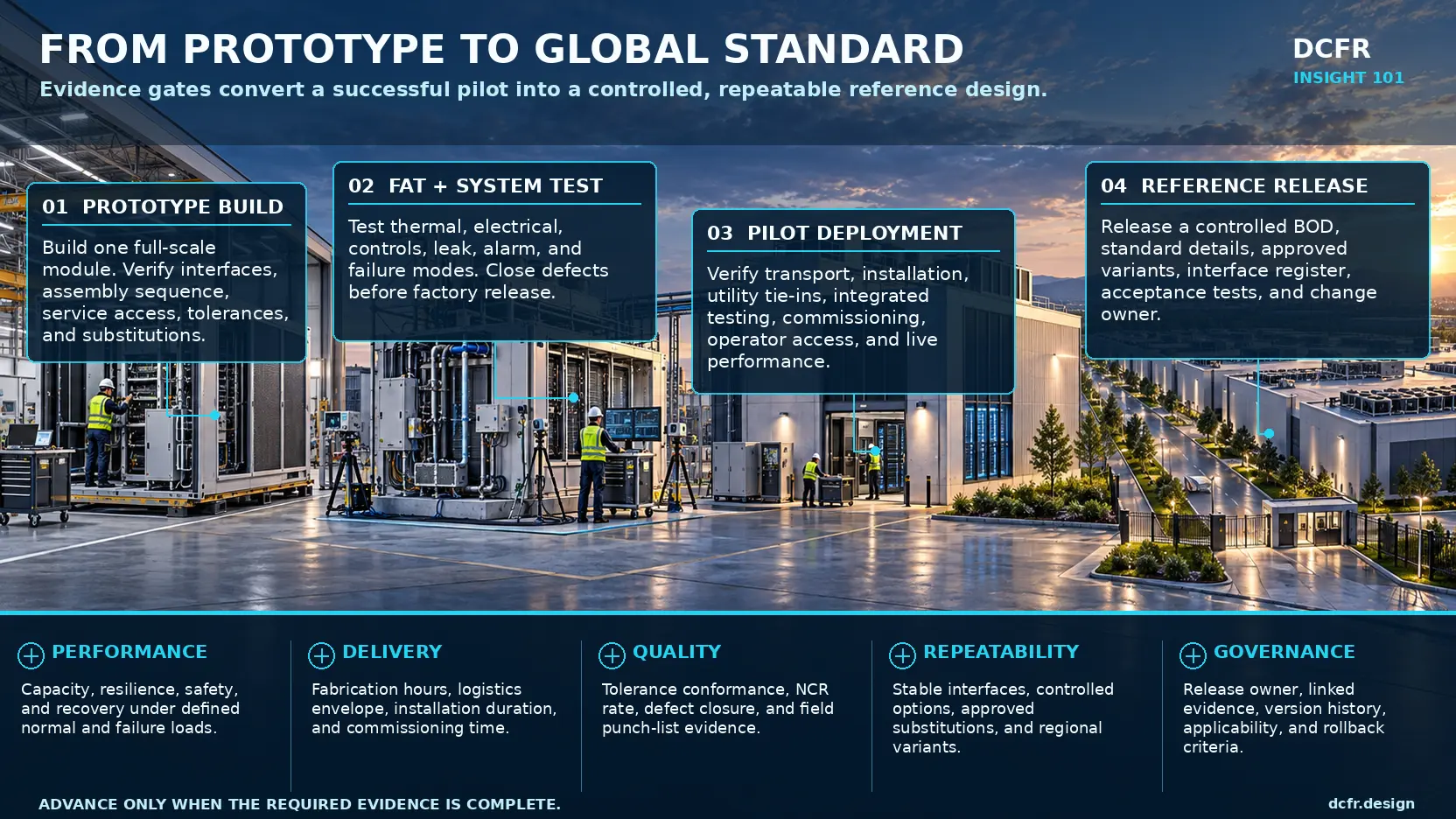
The pilot introduces variables the factory cannot reproduce: road constraints, crane setup, weather, storage, utility readiness, local labor, inspection practice, site tolerances, incomplete predecessor work, live commissioning interfaces, and operating-team readiness. Its purpose is to prove the complete delivery system, not simply repeat the factory test.
Track planned versus actual fabrication, installation, energization, and commissioning duration; labor by factory, site, discipline, and rework category; shipping damage and preservation; first-fit connection success; requests for information; nonconformance reports; punch-list items; temporary works; field modifications; and operational acceptance findings.
The essential review question is not whether the pilot opened. It is which outcomes came from the design and which depended on exceptional people, favorable conditions, or undocumented intervention. A pilot that passes through heroics has produced valuable learning, but it has not yet produced a repeatable standard.
Five Evidence Gates Control the Path to Scale
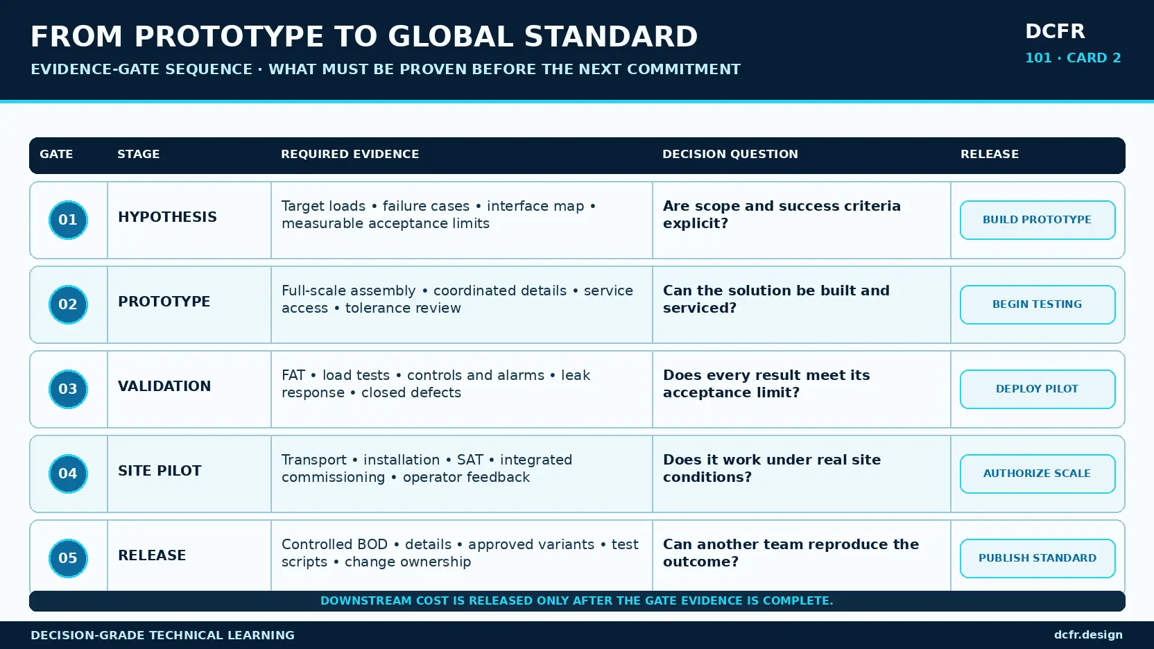
Evidence gates prevent schedule pressure from turning an unresolved assumption into a portfolio standard. Gate 1 authorizes a prototype when requirements, high-risk interfaces, instrumentation, and pass criteria are defined. Gate 2 authorizes formal testing when the as-built configuration, inspections, deviations, and calibration records are controlled. Gate 3 authorizes the pilot when critical failure modes have been exercised and severe defects are closed.
Gate 4 authorizes scale only after site delivery, commissioning, operations, maintenance, and recovery have been demonstrated, and only after pilot exceptions are incorporated or expressly excluded. Gate 5 publishes the reference when the release owner accepts the complete bill of evidence, applicability limits, approved variants, residual risks, version history, and rollback plan.
Each gate requires a named decision authority and explicit stop conditions. A completed calendar milestone is not evidence. If success cannot be measured, configuration cannot be reconstructed, or critical defects remain open, the correct gate decision is hold—not conditional approval hidden in meeting minutes.
 Open full-size plan ↗
Separate Global Core, Controlled Variants, and Site Adaptations
Global programs fail when they allow everything to vary or freeze everything. Unlimited variation forces each site to repeat option studies, coordination, procurement decisions, and risk discovery. Excessive rigidity forces teams to create unofficial deviations when the reference conflicts with climate, grid, code, water, labor, logistics, or supply-chain conditions.
The global core should protect the performance and interface logic that makes the platform repeatable: resilience philosophy, functional topology, principal planning rules, safety-critical details, controls intent, and acceptance logic. Controlled variants should provide pre-engineered options for voltage, cooling, climate envelope, equipment families, structural hazards, and regional compliance pathways. Site adaptations should address the parcel, utility point of connection, grading, routing, planning conditions, and local hazards within defined boundaries.
Every variant needs an applicability statement, affected requirements, supporting evidence, changed interfaces, incompatible combinations, and an approval owner. A menu of options without combination rules is another form of uncontrolled design.
Reference Design Control Layers
| Layer | Purpose | Typical content | Change authority |
|---|---|---|---|
| Global core | Protect repeatable performance and interface logic | Resilience philosophy, functional topology, planning rules, critical interfaces, controls intent, acceptance logic | Central design authority |
| Controlled variants | Adapt through pre-engineered and tested options | Voltage families, cooling options, climate packages, approved alternates, regional compliance pathways | Central authority with regional technical approval |
| Site adaptations | Respond to parcel- and authority-specific conditions | Grading, utility connection, external routing, planning conditions, local hazards and access | Project authority within defined boundaries |
Interfaces Deserve More Attention Than Components
Most reference-design failures do not originate inside a well-specified component. They emerge at boundaries: utility service to campus architecture; manufacturer skid to field distribution; technology cooling to facility cooling; local controls to supervisory controls; module to structure, enclosure, and fire compartment; tested firestop to real mixed-service penetration; replacement path to architectural clearance; and commissioning script to the actual sequence of operation.
Treat each critical interface as a technical contract. Define the physical boundary, owners on both sides, functional inputs and outputs, capacity range, load or pressure envelope, dimensional tolerance, signals and protocols, failure behavior, inspection, test, required data, and change-notification rule.
An interface is not stable because a line appears on a drawing. It is stable when both sides can change within defined limits without surprising the other. Stable interfaces create leverage: vendors can improve components, regions can select approved variants, and future phases can expand without reopening the complete system architecture.
Release Readiness Requires Converging Evidence
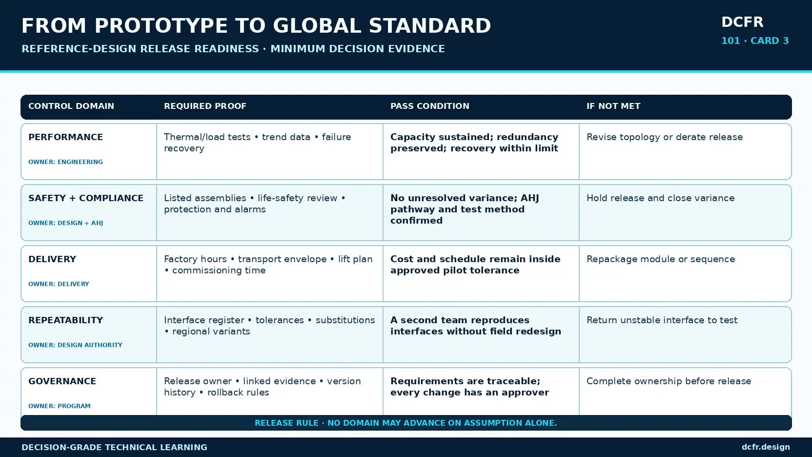
A global reference should not be released on the strength of one headline result. Performance evidence must cover capacity, efficiency, resilience, transition behavior, maintenance states, selected failures, and recovery. Safety and compliance evidence must identify the approval path, tested or listed assemblies, inspection dependencies, authority assumptions, and regional deltas.
Delivery and quality evidence should track fabrication hours, logistics constraints, installation duration, tolerance conformance, first-fit success, nonconformance, rework, defect closure, and commissioning readiness. Repeatability evidence should show that a second qualified team can deliver the package without relying on the pilot designers' tacit knowledge.
Governance evidence must identify the release owner, version history, linked evidence, applicability, exception process, change classification, approvers, and rollback criteria. Configuration management keeps a validated baseline from drifting through a series of individually reasonable but collectively damaging changes.
Minimum Release Evidence
| Domain | Required proof | Pass condition | Hold or reject when |
|---|---|---|---|
| Performance | Capacity, efficiency, transition, failure and recovery test data | Requirements pass at controlled operating points with anomalies closed | Only nominal steady-state performance is shown |
| Safety + compliance | Code path, tested assemblies, inspections, authority assumptions and regional deltas | Approval basis is explicit and transferable evidence is separated from local confirmation | One jurisdiction's acceptance is assumed to apply globally |
| Delivery + quality | Fabrication, logistics, first-fit, installation, NCR, rework and commissioning metrics | Process is repeatable without exceptional recovery effort | Schedule success conceals undocumented rework or intervention |
| Repeatability | Second-team replication and bounded variant combinations | A new qualified team reproduces the intended outcome without redesign | Tacit knowledge remains essential |
| Governance | Owner, version, applicability, evidence links, change and rollback rules | Every release and deviation has accountable approval | Configuration or decision ownership is unclear |
The Second-Team Test Exposes Tacit Knowledge
The strongest repeatability test is to give the controlled package to a qualified team that did not design or deliver the prototype. Measure questions, interpretations, assumptions, workarounds, late decisions, field changes, defects, and redesign required to reproduce the system.
The original team naturally fills gaps from memory. A second team cannot. That makes second-team replication more than a quality check: it is a practical test of whether knowledge has moved from people into the product system.
Do not score the test only by final completion. Track where the team paused, which interfaces generated multiple interpretations, which details required direct designer input, which tests could not be executed as written, and which local adaptations unintentionally changed the performance basis. Those are release defects even if the building ultimately operates.
 Open full-size plan ↗
Build a Bill of Evidence
Every release should include a navigable index connecting each critical requirement to its design response, calculation, inspection, test result, deviation, and approval. This converts a document library into an engineering argument and allows an owner to understand not only what the standard contains, but why it is trusted.
For example, a requirement for continuous cooling during a defined electrical event should link to the topology, capacity calculation, sequence of operation, control cause-and-effect, test procedure, tested configuration, raw data, anomalies, corrective actions, and signed acceptance. If a later change affects any item, the link shows which evidence must be reviewed or repeated.
At minimum, record the requirement and source, owner and criticality, satisfying design element, verification method, acceptance threshold, validation scenario, supporting evidence, configuration tested, deviations, residual risks, approver, release applicability, change impact, and retest status.
Make the Reference Design Learn Across Deployments
The next generation of reference design should do more than control PDFs. A requirement-to-evidence digital thread can carry stable identifiers through models, schedules, submittals, inspections, tests, and operational data. Interface passports can make geometry, ownership, limits, signals, failure behavior, and tests explicit at every critical boundary.
Variant eligibility rules can screen climate, utility, water, code, hazard, and supply-chain conditions, preventing incompatible option combinations before detailed design. Portfolio defect heat maps can normalize RFIs, nonconformance, commissioning anomalies, and alarms against standard details and interfaces, revealing recurring problems that individual project closeout reports conceal.
Drift detection can compare each issued project configuration with the approved reference and flag changed equipment, sequences, assemblies, interfaces, or test omissions. Human design authority should remain responsible for approval; automation should expose change and evidence impact, not make the technical decision.
Use major, minor, and corrective releases. Major releases change the platform or performance basis. Minor releases add bounded compatible capability. Corrective releases close defects without changing intended function. Every release should identify affected requirements, variants, projects, procurement packages, tests, and rollback conditions.
Know What Must Stop a Release
Explicit stop conditions protect the portfolio when schedule and capital pressure rise. Hold the release when a safety- or resilience-critical failure remains open; a critical requirement has no objective threshold; the tested configuration cannot be reconstructed; the pilot depended on undocumented field redesign; controls passed only after bypass or manual override; or a substitution changes performance without new evidence.
Also hold when one authority's approval is assumed to transfer globally, operations cannot safely isolate or replace critical equipment, variant combinations are unbounded, or no owner accepts change and rollback responsibility. Accepted for this pilot and approved for replication are different decisions. The first closes a project issue; the second accepts portfolio exposure.
The Reference-Release Package
A mature release contains the controlled basis of design and requirements; coordinated drawings, specifications, schedules, and model; system and interface architecture; core, variant, and site-adaptation matrix; approved equipment families and substitution boundaries; assumptions and applicability limits; prototype, factory, site, and integrated-systems-test scripts; and the requirements-to-evidence index.
It should also include fabrication, transport, lifting, installation, and replacement strategies; regional code and authority assumptions; cost and schedule ranges with their conditions; residual risk and technical debt; commissioning and operational acceptance; training requirements; release notes; version history; change approval; rollback plan; and a named design authority with a defined review cadence.
ISO 9001 frames quality management as an organizational system rather than a final inspection activity. The same logic applies here: competence, documented information, controlled processes, corrective action, evidence, and continual improvement must surround the technical package if it is expected to scale.
DCFR Design Principle
The decisive moment in standardization is not the first successful deployment. It is the moment an organization can explain—requirement by requirement and interface by interface—why the design should succeed again.
That confidence does not come from visual consistency, a frozen drawing set, or the reputation of the pilot team. It comes from objective evidence, controlled variation, explicit ownership, and a feedback system that turns every deployment into a better release.
The goal is not to eliminate local engineering. It is to reserve local engineering for genuinely local problems while protecting verified logic that should not be rediscovered.
Early screening checklist
What to verify before advancing this site.
- Define critical requirements, interfaces, test methods, and acceptance thresholds before prototype fabrication.
- Record the exact prototype and pilot configurations, including deviations, software, instruments, and approved substitutions.
- Exercise normal, maintenance, selected failure, recovery, and operational acceptance conditions.
- Classify every pilot finding as baseline correction, controlled variant, site adaptation, or accepted residual risk.
- Separate the global core from regional variants and site-specific adaptations with explicit applicability rules.
- Run a second-team replication test to expose tacit knowledge and ambiguous interfaces.
- Link every critical requirement to design response, evidence, approval, and retest status.
- Name the release owner and define versioning, exception, change, applicability, and rollback rules.
What DCFR would flag
Risks surfaced at the screening stage.
DCFR would flag a proposed reference release when the pilot succeeded but critical requirements, tested configuration, exceptions, variant boundaries, second-team repeatability, or change ownership remain undocumented.
Professional confirmation required
Items requiring licensed validation.
Final release requires project- and region-specific confirmation by the responsible owner, design professionals, manufacturers, commissioning authority, operators, utilities, insurers where applicable, and Authorities Having Jurisdiction. Referenced standards and guidance do not replace contractual, statutory, listing, certification, or project-specific requirements.
Final takeaway
A PILOT PROVES ONE OUTCOME. A GLOBAL REFERENCE DESIGN PROVES THAT THE OUTCOME CAN BE REPRODUCED, GOVERNED, AND IMPROVED.
Screen up to 20 candidate sites before selecting one for the full DCFR report.
Each DCFR Report Package includes a preliminary 20-site comparison PDF / export package plus one selected planning-grade feasibility report.