
DCFR Insight 102 / Cooling & Water
Liquid Cooling Is an Architectural System
Why high-density cooling must be designed through the building section—from silicon and coolant loops to structure, drainage, controls, heat rejection, maintenance, and recovery—not added at the rack.
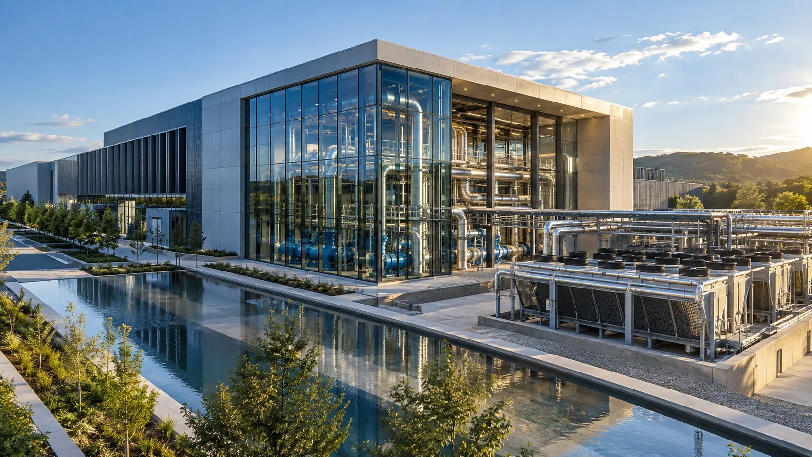
The Rack Is Only One Segment of the Thermal Path
Liquid cooling begins at the chip, but its consequences extend through the rack, room, structure, drainage, controls, heat-rejection plant, operating model, and future expansion strategy. The common mistake is to treat it as an equipment substitution: replace air-cooled servers with liquid-cooled racks, add a coolant distribution unit, connect pipes, and continue with the original building design.
That approach fails because the real system starts where heat is captured at the processor and ends where the site rejects, stores, or reuses it. Between those points are hydraulic boundaries, control systems, isolation zones, structural loads, maintenance activities, failure paths, and ownership handoffs. At AI densities, those decisions affect floor-to-floor height, structural grids, ceiling congestion, slab loads, housekeeping bases, rated penetrations, drainage, plant adjacency, lifting access, and the sequence in which the building can be commissioned and expanded.
The planning question is not which liquid-cooling product to buy. It is what building, operating model, and failure architecture are required to support the intended compute platform throughout its life. Product selection should follow that system definition, not substitute for it.
Define the Complete Thermal Path
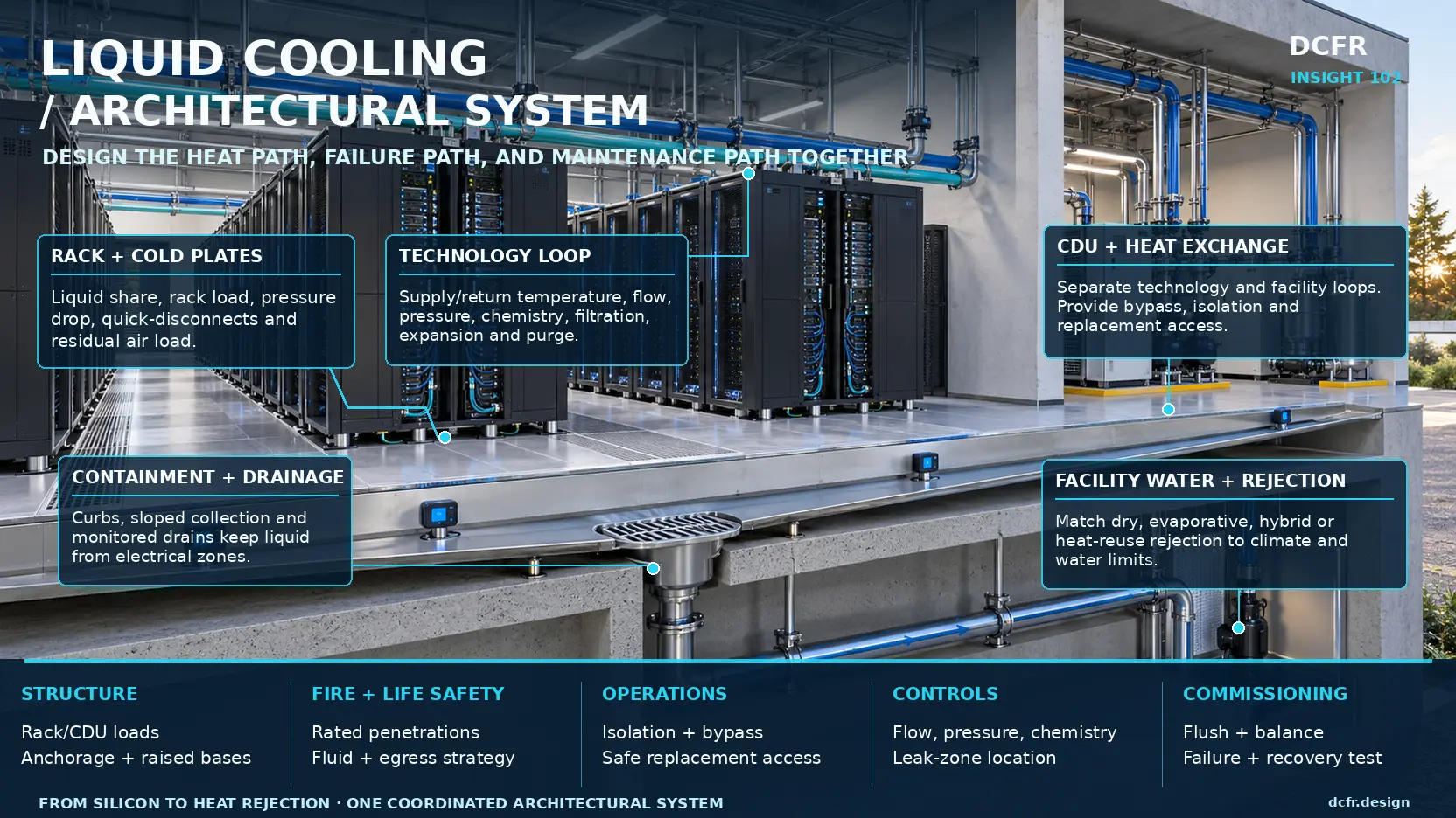
A robust architecture separates the system into five connected layers: the silicon and cold-plate interface, the technology cooling system, the coolant distribution unit, the facility-water system, and heat rejection or heat use. Each layer has different limits, owners, failure behavior, and evidence requirements.
At the rack, declare the design and credible peak heat output, the fraction captured by liquid, the residual air load, supply and return temperatures, flow, pressure drop, coolant chemistry, wetted materials, quick-disconnect arrangement, branch isolation, permissible temperature excursion, and service procedure. A rack described as liquid cooled is not necessarily free of air cooling; memory, storage, power conversion, networking, and other components may still reject heat to the room. The residual load determines whether room air systems can be reduced and whether a later IT refresh could exceed their capacity.
The technology cooling system should keep routes short and pressure losses controlled while leaving manifolds, valves, filters, sensors, vents, and drains accessible. Above-rack, below-floor, trench, and side-fed arrangements distribute risk differently. Every route must show how a leak is located, how a useful zone is isolated, how trapped fluid is drained and air purged, and how components are replaced without dismantling unrelated systems.
The CDU is a hydraulic and operational boundary, not merely a pump skid. Its location—in rack, in row, in a service gallery, or at plant level—sets the size of the failure domain, distribution distance, white-space exposure, maintenance clearance, bypass strategy, redundancy, and replacement route. The decision belongs in the building and reliability architecture, not only in a vendor capacity comparison.
On the facility side, the relationship Q = mass flow × specific heat × temperature difference is simple, but the design is not. Temperature difference, pump energy, cold-plate limits, CDU approach, minimum flow, water chemistry, outdoor conditions, and failure response must work as one envelope. Warm-water operation may extend economizer hours and improve heat-reuse potential, but liquid cooling does not automatically eliminate compressor energy or site water use; those outcomes depend on the rejection system and operating temperatures.
 Open full-size plan ↗
Choose a Cooling Architecture—and Accept Its Operating Model
Direct-to-chip, immersion, rear-door heat exchangers, and hybrid systems do not merely move heat differently. They create different room geometries, service procedures, fluid responsibilities, fire strategies, replacement paths, and staffing requirements.
Direct-to-chip cooling is generally the most compatible with conventional rack operations. It targets the highest heat-flux components while retaining air cooling for residual loads, which makes it useful for phased conversion and hybrid halls. Its hidden difficulty is interface multiplication: cold plates, internal hoses, quick disconnects, rack manifolds, branches, CDUs, controls, and water-quality requirements may cross several vendor boundaries. End-to-end compatibility needs a named owner.
Immersion cooling replaces the rack-aisle service model with tanks, dielectric fluid, lifting, draining, filtering, component staging, and wet-hardware handling. Tank grids need safe working clearances, overhead lifting coverage, spill containment, fluid-service space, fire-engineering review, and controlled logistics. It can be powerful for stable specialist compute, but it should not be inserted into a room planned for conventional front-and-rear rack service.
Rear-door heat exchangers can raise density in existing halls without taking coolant to the processor. They also add weight, depth, door swing, hose routing, and maintenance constraints behind every rack. Hybrid estates may operate air-cooled legacy racks, direct-to-chip AI racks, and rear-door systems for years. The building should zone and meter those conditions so the least efficient zone does not control the whole plant.
Liquid-Cooling Architecture Comparison
| Architecture | Best fit | Building implications | Primary risk to resolve |
|---|---|---|---|
| Direct-to-chip | High-density GPU/HPC and repeatable rack platforms | Segregated loops, CDU access, residual-air capacity, branch containment and drainage | End-to-end ownership across multiple equipment and coolant interfaces |
| Immersion | Specialized compute with stable hardware and a dedicated operating model | Tank grid, lifting coverage, fluid service, spill control, staging and fire review | Material/fluid lifecycle and unfamiliar maintenance workflow |
| Rear-door heat exchanger | Staged retrofit and mixed-density halls | Door depth and swing, hose routing, rear-aisle access and added rack load | Service obstruction and dependence on legacy room-air conditions |
| Hybrid estate | Phased conversion and colocation with mixed IT generations | Zoned halls, independent metering, modular CDUs, convertible routes and coordinated controls | The least efficient zone controlling plant operation |
Use the Building Section as the Coordination Model
A plan can show racks and pipe routes; the section reveals whether the system can be built, inspected, serviced, and expanded. The coordinated section should establish rack, manifold, busway, cable tray, sprinkler, lighting, sensor, structural-support, and seismic-bracing zones, together with safe access to valves, filters, vents, drains, and overhead equipment.
It should also resolve curbs, thresholds, slab depressions, drainage gradients, separation from vulnerable electrical equipment, rated penetrations, CDU bases, pull space, heat-exchanger access, pipe expansion, anchors, guides, high and low points, and routes for future headers. The service position matters as much as the installed position: a valve that fits but cannot be operated, a filter with no removal path, or a CDU that requires façade demolition for replacement is an architectural defect.
The section should be tested against multiple states: initial installation, normal operation, planned maintenance, a credible leak, component removal, and the future expansion configuration. Reserving abstract space is insufficient unless structural capacity, access, shutdown boundaries, and connection interfaces are also reserved.
Design the Failure Architecture Before the Nominal System
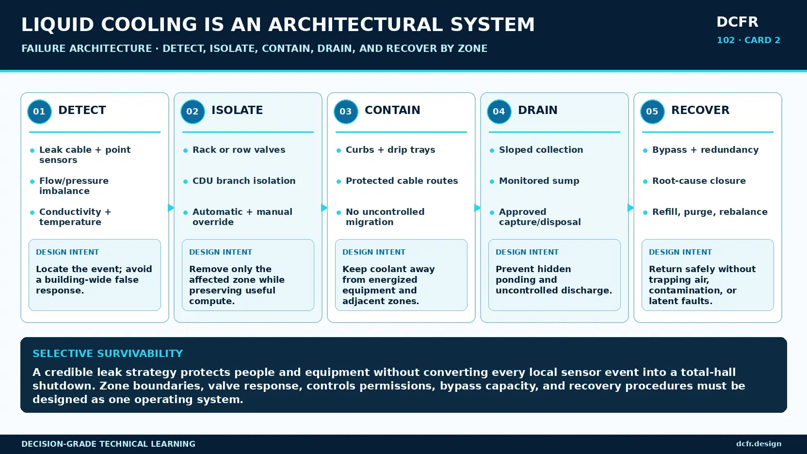
Bringing liquid close to critical electronics requires a selective, observable, contained, and recoverable failure system. Resilience is not achieved by saying that leaks are unlikely or by placing a single cable sensor beneath a row.
Detection should combine local fluid sensing with hydraulic evidence such as flow, differential pressure, level, conductivity, and temperature trends. Controls should distinguish a sensor fault from a confirmed leak and locate the event to a rack, branch, row, or room. Isolation boundaries must match the acceptable business failure domain; if a rack event shuts an entire hall, the zoning is too coarse for many mission-critical uses.
Containment must stop liquid from reaching energized equipment, crossing fire compartments, entering concealed construction, or migrating through penetrations. Curbs, trays, thresholds, sleeves, protected cable routes, and sloped surfaces must form a continuous physical argument. Drainage needs a known destination and should distinguish routine drain-down, minor leakage, major release, and fire water. Disposal requirements must reflect the actual coolant chemistry.
Recovery requires bypass capacity, spares, compatible refill fluid, filtration, purge capability, a recommissioning sequence, and authority to return the zone to service. A safe shutdown is only the start. The architecture must recover within the business-continuity requirement, and that recovery must be demonstrated rather than assumed.
 Open full-size plan ↗
Treat Water Quality as a Reliability System
Many failures attributed to liquid cooling are failures of materials, cleanliness, or ownership. Mixed metals, incompatible elastomers, oxygen ingress, construction debris, incorrect inhibitor concentration, microbiological growth, poor filtration, and uncontrolled make-up water can undermine a sound topology.
The owner needs one water-quality authority across design, procurement, construction, commissioning, and operations. That authority should control permitted wetted materials, coolant recipe, fill-water quality, cleaning and flushing, filtration, sampling locations and frequency, acceptance limits, storage life, corrective action, and warranty implications.
The boundary between IT-vendor requirements and facility-water requirements deserves explicit reconciliation. Individual products meeting their own specifications does not prove interoperability. Record the tested fluid, materials, filtration, software, instruments, and operating condition so later substitutions can be evaluated against real evidence.
Greenfield: Design for Bounded Conversion
A new facility should avoid locking the building to one rack generation or one exact CDU frame. Durable investments include pipe corridors and supports sized for defined future phases, repeatable connection zones at hall boundaries, plant bays for additional or replacement CDUs, extendable routes that do not require shutdown of live halls, and drainage and containment designed before equipment selection.
The goal is bounded adaptability—not unlimited flexibility. Define credible future states, their loads, geometry, temperature envelopes, residual-air needs, connection standards, and controls interfaces. Reserve what those states require and explicitly exclude the rest. This prevents speculative overbuilding while protecting the upgrades most likely to preserve the campus's value.
Plan temperature and metering architecture for possible heat recovery, but do not compromise data-center reliability for a theoretical customer. Heat-reuse readiness means accessible headers, metering, isolation, space for exchangers or heat pumps, a backup rejection path, and a clear commercial and operating boundary.
Retrofit: Prove the Enabling Works Before Buying Compute
Retrofit studies often confirm that electrical power can reach the rack and understate the cooling enabling works. Feasibility must test heat-rejection capacity and temperature compatibility, occupied-space pipe routes, structural capacity, residual air cooling, leak migration, drainage, rated penetrations, tie-in shutdowns, legacy BMS integration, and equipment rigging and replacement paths.
The retrofit should be reconfigured or rejected when it depends on inaccessible routes, intolerable shutdowns, inadequate residual-air capacity, uncontrolled water paths, or continuous inefficient chiller operation. A successful demonstration rack does not prove that a full hall can be operated and maintained safely.
For mixed halls, create explicit zones with independent metering and service rules. Modular CDUs, convertible service corridors, and reserved branch points can reduce stranded work when tenant and IT refresh cycles do not align with building replacement cycles.
Commission Before Filling—and Test Recovery
Liquid-cooling commissioning begins with design review and construction cleanliness, not with a final functional test. The program should verify topology, materials, pressure class, expansion, isolation, drainage, instrumentation, access, and control narratives before fabrication and installation.
Factory tests should exercise CDU capacity, pump transitions, alarms, interlocks, heat-exchanger performance, and simulated sensor or component failures. Construction controls should cover capped piping, storage, joint inspection, flushing velocity, temporary strainers, debris removal, pressure testing, and water-quality acceptance before sensitive IT equipment is connected.
Integrated testing should prove worst-path flow, branch balance, redundant configurations, every alarm and isolation command, communication loss, bypass, manual override, thermal transients, maintenance states, credible failures, and recovery. Finish with an operational drill: detect a leak, isolate the zone, capture fluid, repair, refill, purge, recommission, and return it to service.
 Open full-size plan ↗
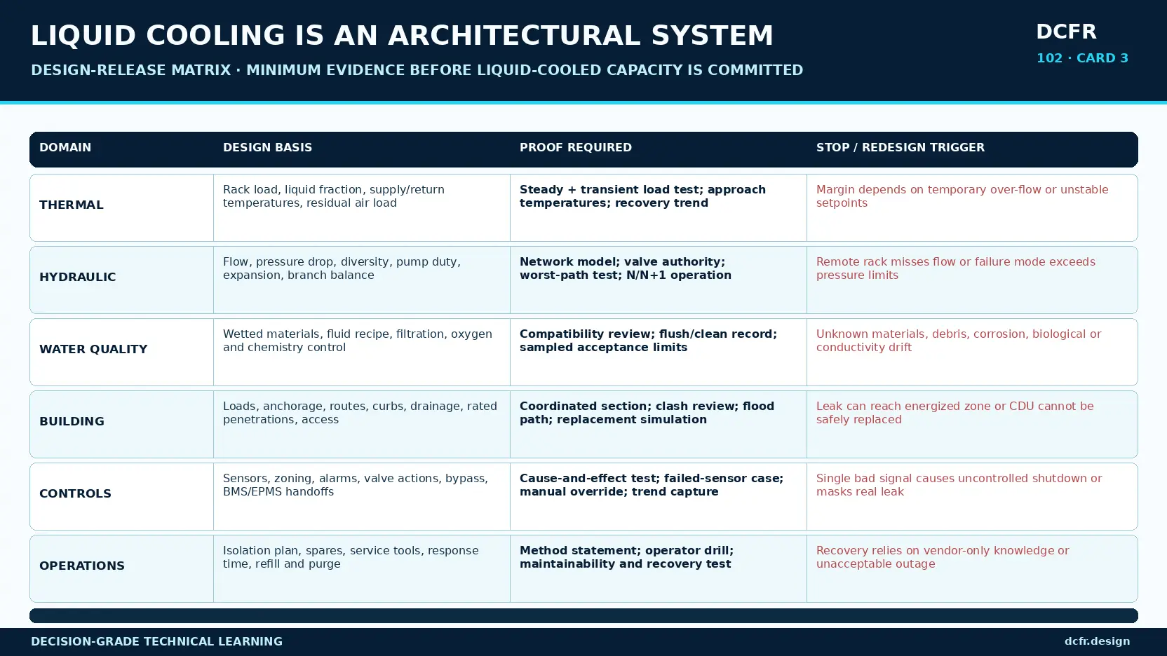
Minimum Design-Release Evidence
| Domain | Minimum decision evidence | Stop or redesign trigger |
|---|---|---|
| Thermal | Rack load, liquid fraction, temperatures, flow, residual air, steady and transient tests | Performance requires unstable setpoints or temporary over-flow |
| Hydraulic | Network model, worst-path test, pump duty, pressure limits, branch balance and redundancy | Remote racks miss flow or a failure state exceeds equipment limits |
| Water quality | Wetted-material review, cleaning/flushing record and samples within limits | Unknown materials, debris, corrosion, biological or conductivity drift |
| Building | Coordinated section, loads, rated penetrations, containment, drainage and replacement simulation | A leak can reach energized systems or equipment cannot be replaced safely |
| Controls | Cause-and-effect matrix, sensor-failure tests, selective isolation, overrides and trends | One bad signal causes uncontrolled shutdown or conceals a real leak |
| Operations | Isolation plan, spares, response drill, refill/purge method and recovery test | Recovery depends on undocumented knowledge or exceeds outage tolerance |
Release Only When Six Evidence Domains Converge
A liquid-cooled platform should not be released on the strength of one thermal test. Thermal, hydraulic, water-quality, building, controls, and operational evidence must describe the same controlled configuration and the same operating envelope.
Thermal evidence should cover rack load, liquid fraction, supply and return temperatures, residual air load, steady operation, transients, and recovery. Hydraulic evidence should cover the network model, worst path, pump duty, pressure limits, branch balance, minimum flow, and redundancy. Water-quality evidence should establish materials compatibility, cleaning, flushing, filtration, and sampled acceptance.
Building evidence should prove structural loads, coordinated sections, rated penetrations, containment, drainage, access, and replacement. Controls evidence should demonstrate cause and effect, selective isolation, sensor failures, trends, overrides, and communications loss. Operational evidence should prove response, spares, refill, purge, repair, recommissioning, and recovery time.
Five Innovations Worth Designing Now
The strongest opportunities do not come from adding novelty to the rack. They come from making the surrounding architectural platform more measurable, replaceable, and adaptable.
First, define thermal zones as a capacity product: supply temperature, pressure envelope, redundancy, residual-air capacity, and service model can become a verified offer matched to a compute platform. Second, concentrate manifolds, sensors, isolation, drains, and controls in replaceable cooling spines so the distribution layer can be upgraded without reopening every rack connection.
Third, plan temperature cascades deliberately. Higher-temperature return water may support useful heat recovery before final rejection while colder loads remain segregated. Fourth, extend hydraulic digital twins to model leak consequence: migration path, sensor response, exposed electrical systems, valve isolation, and recovery time. Fifth, make the architecture commissioning-ready with permanent test points, sample ports, visible flow direction, drain and fill stations, and safe failure-injection provisions.
The Planning-Grade Gate
Before committing liquid-cooled capacity, the owner should be able to identify the compute and rack heat envelope, liquid fraction and residual air load, end-to-end interface owner, technology/facility loop boundary, CDU failure domain, and the method for detecting, isolating, containing, draining, and recovering a leak by zone.
The team should also prove that every maintainable component can be reached and replaced safely; that the operating temperature unlocks the intended economization or heat-reuse benefit; that mixed air- and liquid-cooled generations can coexist; and that hydraulic, thermal, controls, water-quality, building, and recovery performance have objective acceptance evidence.
Finally, define which future expansion states are physically reserved and which are excluded. If those questions cannot be answered, the project has a cooling concept—not a liquid-cooling architecture.
DCFR Design Principle
Liquid cooling can unlock higher compute density, lower fan energy, warmer rejection temperatures, and new heat-reuse opportunities. None is automatic. Each depends on the building and operating system surrounding the rack.
The most resilient projects coordinate three paths: the heat path from silicon to rejection or reuse; the failure path from detection to selective recovery; and the maintenance path from isolation to safe replacement. When those paths are resolved through the building section, liquid cooling becomes a controlled architectural platform for future compute—not a collection of wet components added late in design.
Early screening checklist
What to verify before advancing this site.
- Declare the compute envelope, liquid-captured fraction, residual air load, temperatures, flow, pressure, and allowable excursions.
- Define the technology/facility loop boundary and assign end-to-end ownership for compatibility and water quality.
- Coordinate rack, piping, electrical, fire, structure, drainage, access, and future expansion in building section.
- Match CDU placement and hydraulic isolation to the acceptable failure domain and maintenance strategy.
- Trace each credible leak from detection through selective isolation, containment, drainage, repair, refill, purge, and return to service.
- Verify wetted materials, cleaning, flushing, filtration, coolant chemistry, sampling, and acceptance before connecting IT.
- Model the installed, service, failure, replacement, and future-expansion positions—not only normal operation.
- Commission thermal, hydraulic, controls, water-quality, building, and recovery performance against one controlled configuration.
What DCFR would flag
Risks surfaced at the screening stage.
DCFR would flag a liquid-cooling proposal when rack technology is selected before the thermal path, residual air load, hydraulic zones, containment, drainage, controls, maintenance access, water-quality authority, and recovery evidence are defined.
Professional confirmation required
Items requiring licensed validation.
Final design requires project-specific confirmation by the owner, IT and cooling-equipment manufacturers, design professionals, commissioning authority, operators, insurer where applicable, and Authorities Having Jurisdiction. Coolant chemistry, material compatibility, fire classification, environmental disposal, equipment limits, and test procedures must be verified for the selected platform and site.
Final takeaway
LIQUID COOLING IS NOT A RACK ACCESSORY. IT IS A BUILDING-SCALE HEAT, FAILURE, AND MAINTENANCE ARCHITECTURE.
Screen up to 20 candidate sites before selecting one for the full DCFR report.
Each DCFR Report Package includes a preliminary 20-site comparison PDF / export package plus one selected planning-grade feasibility report.