
DCFR Insight 60 / Resilience + Operational Risk
Data Center Common-Mode Failures, Cascading Outages, and Recovery Planning
Redundant equipment is only the starting condition. Resilience depends on whether supposedly independent paths remain separate through controls, maintenance, external dependencies, abnormal transitions, and the difficult work of restoring service.
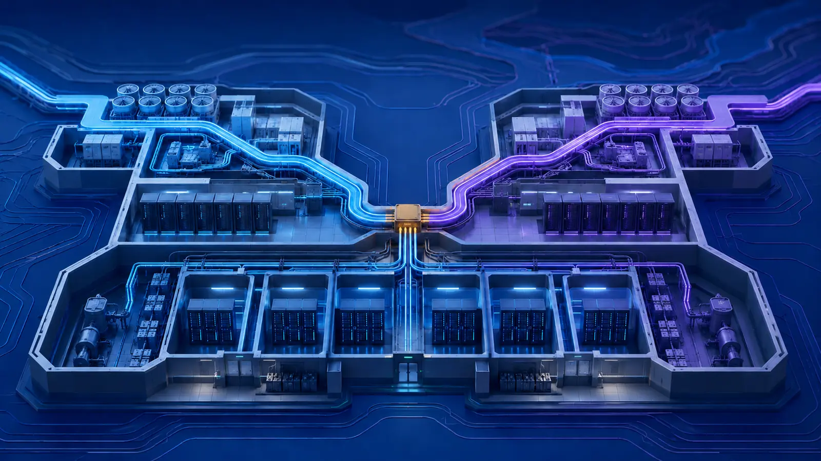
Name the failure mechanism before prescribing more redundancy
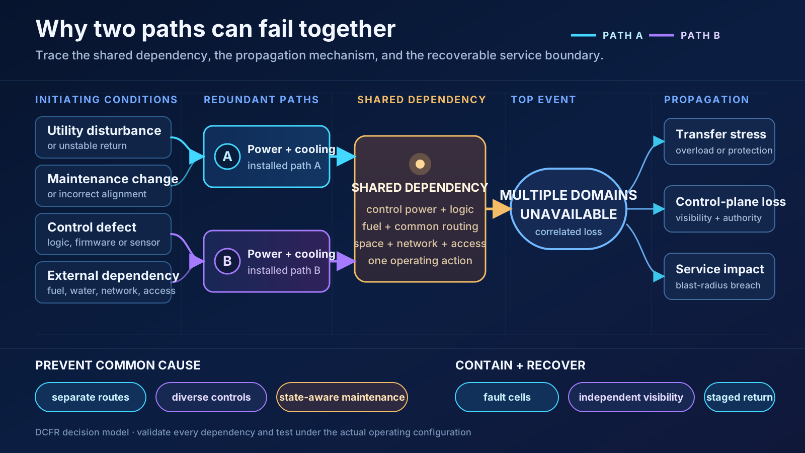
Redundancy means alternate components or paths are available to preserve a required function. A common-cause failure disables two or more nominally independent elements through one shared physical, logical, environmental, or organizational dependency. A cascading failure begins locally and propagates as transfers, protection actions, automation, retries, heat, or operator interventions impose new stress elsewhere. Blast radius is the maximum facility and customer service exposed to one initiating event or change. Recoverability is the demonstrated ability to detect, contain, stabilize, restore priority service, and reconstitute capacity safely. These terms are not interchangeable. Uptime Institute's 2026 analysis says per-site outage frequency continues to decline, yet about one in ten respondents characterized their latest outage as serious or severe; among reported major outages, 57% exceeded $100,000 and one in five exceeded $1 million. Those are industry observations—not a probability forecast for a particular design.
Prove independence across every layer—not just on the one-line diagram
Trace each required service from utility and fuel supply through switchgear, UPS, distribution, cooling, controls, network, workload, and operator action. Record shared substations, ducts, risers, rooms, fire zones, pipe headers, tanks, pumps, batteries, control power, PLCs, firmware, time sources, identity services, monitoring, access systems, vendors, spares, and recovery personnel. Independence must survive the actual cable route, maintenance configuration, software release, and emergency procedure. Tier language is useful but bounded: Uptime describes Tier III as concurrently maintainable while still exposed to equipment failure or operator error, and Tier IV as protecting operation from an individual equipment or distribution-path interruption. Neither statement proves immunity from simultaneous, correlated, external, or software-mediated events outside the assessed scope.
Model a cascade as changing system states
A static N+1 or 2N count says little about the transition from normal operation to utility loss, battery support, generator start, load acceptance, cooling recovery, and return to utility. For every initiating event, model which breakers, valves, controls, network routes, and workloads change state; the timing, ramp rate, protection setting, and capacity margin at each step; and what happens when one expected action is late, partial, or false. A transfer can move healthy load onto a path already weakened by maintenance. Repeated automated retries can convert a transient into sustained congestion. A protective action can preserve equipment while removing multiple services. The analysis must follow dependencies until the system reaches a stable operating state—not stop at the first device that acted correctly.
Define blast radius from the service promise backward
Start with the customer impact the business can tolerate, then set facility fault-containment zones, power and cooling cells, network failure domains, control-plane boundaries, and workload placement to keep one event inside that limit. State whether the protected unit is a rack, hall, building, availability zone, campus, or business service. Physical separation does not guarantee service separation if both cells depend on the same DNS, identity, monitoring, orchestration, spare inventory, or operating team. Conversely, partial service can remain available even when a facility system is impaired if workloads degrade gracefully and recovery dependencies stay reachable. Test the blast-radius claim for normal, maintenance, expansion, and emergency configurations; the temporary topology may be less contained than the permanent design.
Failure-Mechanism Diagnostic Matrix
| Mechanism | Defining behavior | Question that exposes it | Evidence required |
|---|---|---|---|
| Single-component failure | One item fails without disabling its alternate | Can the alternate carry required load in the current state? | Capacity test, protection study and witnessed transfer |
| Common-cause failure | One dependency disables multiple nominally redundant elements | What physical, logical, external or organizational element is shared? | End-to-end dependency map and correlated-failure test |
| Cascading failure | An initiating event propagates through changing loads, controls or protection | What new stress does every automatic or manual action create next? | State-transition model, time sequence and fault-injection result |
| Blast-radius breach | Impact escapes the intended containment cell | Which customer services—not only assets—share this failure domain? | Service map, fault-containment boundary and degraded-mode test |
| Recovery failure | Initial fault is contained but service cannot be restored safely | Do recovery tools, access, staff and dependencies survive the same event? | Rehearsed recovery sequence with release gates and retained evidence |
A single event may involve several mechanisms. Classify each stage separately so the corrective action addresses propagation and recovery—not only the initiating component.
Power systems still dominate—and the maintained state decides the outcome
Uptime Institute's 2026 outage analysis continues to identify power as the leading cause of impactful outages, with UPS, transfer equipment, and generators prominent within that category. The useful response is not simply another generator. Verify protection selectivity, control power, battery autonomy under aged and actual load, generator start and synchronization, load-step acceptance, fuel quality and replenishment, emissions constraints, paralleling logic, grounding, maintenance bypass, black-start sequence, and the ability to return from emergency power without an uncontrolled second transition. Treat the current operating alignment as a controlled configuration. A fully redundant installed plant can behave like a single-path system when equipment is isolated, a tie is closed, a bypass is engaged, or one common controller owns both paths.
Cooling, controls, networks, and access can couple electrical domains
Map thermal and digital dependencies with the same rigor as the electrical one-line. Separate power paths may feed cooling branches that share a condenser-water loop, dry-cooler control panel, make-up source, common header, leak-detection system, or supervisory sequence. Redundant plant may depend on one BMS network, time service, authentication platform, remote gateway, configuration database, or firmware image. During a disturbance, loss of telemetry can hide the state needed to operate manually; loss of electronic access can delay physical intervention. Public incident reports from AWS and Meta illustrate mechanisms in which retries amplified congestion, monitoring or deployment tools shared the affected network, and primary plus out-of-band access became unavailable. These reports demonstrate possible dependency patterns, not general outage probabilities.
Treat maintenance and procedures as changes to the resilience architecture
Every planned isolation temporarily redraws the system. Before work begins, publish the maintained-state one-line, available capacity, prohibited concurrent work, affected alarms and interlocks, compensating controls, weather and load limits, communications plan, rollback point, and emergency restoration route. Use a reviewed method of procedure for the change, standard operating procedures for stable modes, and emergency operating procedures for abnormal states; make roles and command authority unambiguous. Uptime's 2026 analysis identifies failure to follow established procedure as the leading driver within human-error-related outages, while also noting unclear and inconsistent processes. The control is a usable system of preparation, peer check, hold points, situational awareness, and stop-work authority—not a long document opened for the first time during an alarm.
Commission the complete ecosystem in abnormal modes
Component factory tests and normal-mode startup cannot prove integrated resilience. Mission-critical commissioning should exercise the full facility ecosystem at representative load: utility interruption, delayed generator, failed UPS module, weak battery string, stuck breaker or valve, failed sensor, control-network isolation, cooling restart, loss during maintenance, manual operation, return to utility, and controlled shutdown. Verify electrical and thermal stability, alarm sequence, event time synchronization, operator information, access, communications, and the intended containment boundary. Uptime Institute recommends simulated component and system failures and full testing of critical systems rather than representative sampling. Repeat affected scenarios after controls, firmware, wiring, protection, or sequence changes; a successful test belongs to the tested configuration, not to the building forever.
Engineer recovery as a separate capability from ride-through
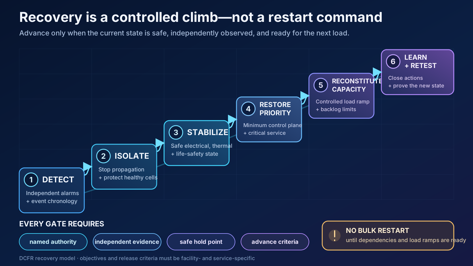
Surviving the first minutes and restoring a complex service are different objectives. Define independent detection, event chronology, isolation criteria, safe electrical and thermal conditions, minimum viable control plane, priority service order, acceptable data state, dependency availability, load-ramp limits, backlog handling, and reconstitution gates. Preserve an incident channel, runbooks, credentials, drawings, contact information, and diagnostic tools outside the failure domain they must repair. NIST contingency guidance distinguishes testing and exercises from full-scale failover and reconstitution for high-impact systems. First-party reports reinforce the principle: Meta described staged restoration to avoid secondary load stress, while Cloudflare's later repeat facility event showed that prior capacity, dependency, and failover improvements could materially shorten control-plane recovery. These cases are design evidence, not universal benchmarks.
Recoverability Release Gates
| Gate | Required evidence | Unsafe shortcut | Primary decision owner |
|---|---|---|---|
| Detect | Independent alarms, synchronized event record and confirmed scope | Acting on one degraded dashboard | Incident commander |
| Isolate | Propagation stopped and healthy cells protected | Opening or closing equipment without an impact model | Authorized facility and network operators |
| Stabilize | Electrical, thermal, fire, fuel and security conditions within limits | Restarting because the initiating alarm cleared | Safety and engineering leads |
| Restore priority service | Minimum control plane and named critical services verified | Bulk restoration before dependencies are ready | Service owner with operations |
| Reconstitute capacity | Controlled load ramp, backlog limits and redundancy restored | Returning all load simultaneously | Incident commander and capacity owners |
| Close and learn | Evidence retained, actions assigned, changes tested and plans updated | Declaring success at first customer recovery | Accountable executive and assurance lead |
Govern recoverability as a living, measured system
Maintain a dependency register, failure-mode library, current-state model, resilience requirements, test matrix, exception log, recovery plan, and corrective-action register under change control. Track untested scenarios, deferred defects, bypass duration, alarm impairment, single points exposed during maintenance, recovery-time performance, failed drills, configuration drift, and overdue actions. Review incidents for mechanism and learning rather than a single convenient root cause: ask what allowed propagation, why containment failed, which recovery tool shared the outage domain, and whether restoration created additional risk. Assign every improvement an owner, due date, verification method, and retest trigger. Redundancy becomes resilience only when independence, containment, and recovery remain demonstrable through construction, operations, expansion, and technology change.
Early screening checklist
What to verify before advancing this site.
- Redundancy, common cause, cascade, blast radius, and recoverability have separate project definitions
- Every required service has an end-to-end physical, logical, external, and organizational dependency map
- Independence claims are verified in normal, maintenance, expansion, and emergency configurations
- Shared control power, logic, networks, fuel, water, space, access, vendors, and recovery tools are identified
- Fault-containment cells are tied to customer-service blast-radius limits
- Protection, transfer, generator, UPS, battery, cooling, and return-to-normal transitions are tested at load
- Cooling and control failures are analyzed alongside electrical and network failure modes
- Method, standard, and emergency procedures include peer checks, hold points, rollback, and stop-work authority
- Integrated systems testing includes delayed, partial, false, and correlated responses—not only clean failures
- Monitoring, communications, credentials, drawings, access, and diagnostic tools survive the domain they repair
- Recovery priorities, load ramps, backlog limits, decision authority, and release gates are rehearsed
- Every incident and material change closes with owned corrective action and a defined retest trigger
What DCFR would flag
Risks surfaced at the screening stage.
DCFR would flag a resilience claim based on N+1, 2N, or a Tier label without an end-to-end dependency map, maintained-state analysis, service-level blast-radius limit, abnormal-mode integrated test, independent recovery tooling, and a demonstrated path from safe isolation through controlled capacity reconstitution.
Professional confirmation required
Items requiring licensed validation.
Confirm resilience objectives, Tier or other certification scope, utility and fuel assumptions, protection settings, environmental limits, fire and life-safety interfaces, cybersecurity, control-system authority, maintenance states, staffing, spares, recovery priorities, test hazards, insurance requirements, and customer service commitments with the owner, operators, customers, utility, network providers, qualified electrical and mechanical engineers, controls and IT teams, equipment manufacturers, commissioning authority, insurer, counsel, emergency responders, and authority having jurisdiction.
Final takeaway
Redundancy limits expected component loss; resilience limits propagation and proves that people, systems, and recovery tools can restore the promised service without creating the next failure.
Screen up to 20 candidate sites before selecting one for the full DCFR report.
Each DCFR Report Package includes a preliminary 20-site comparison PDF / export package plus one selected planning-grade feasibility report.