
DCFR Insight 45 / Prefabricated Modular Systems
Prefabricated Modular Data Center Planning, Delivery, and Commissioning
A modular data center is not a container placed on a pad. It is a factory-manufactured capacity system whose land, backbone, interfaces, logistics, code path, testing, operations, and future expansion must be designed as one delivery architecture.
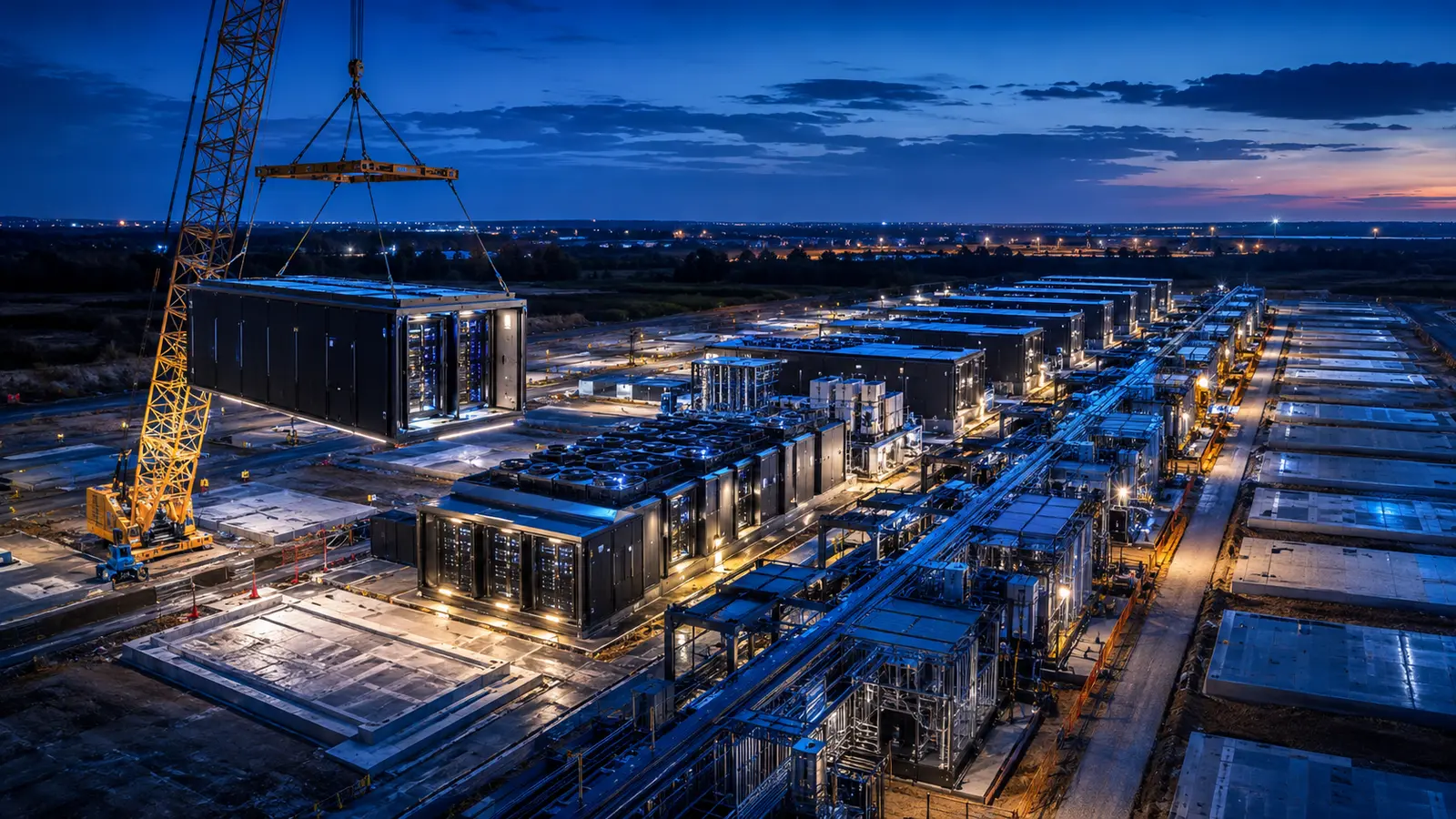
Modular is a delivery architecture—not a container type
Prefabricated modular data centers can range from equipment skids and electrical rooms to integrated information-technology modules or nearly complete facilities. The defining feature is that a functional system or subsystem is engineered, assembled, and tested away from the final site, then transported, connected, and commissioned as part of the permanent facility. A useful plan therefore starts by defining the capacity product, interface boundaries, and acceptance evidence. Calling every enclosure a module hides the decisions that determine whether the project is repeatable, permitted, maintainable, and bankable.
Choose the modularity boundary deliberately
Separate component modules, functional modules, information-technology modules, and complete modular facilities. A conventional shell may receive prefabricated power rooms, cooling skids, multi-trade racks, and pre-integrated white-space assemblies. A remote or small deployment may use an all-in-one enclosure. A hyperscale program may standardize repeatable megawatt blocks while retaining a site-built backbone and weather enclosure. Select the boundary by repetition, vendor capacity, transport envelope, local labor, climate, code treatment, maintainability, technology-refresh frequency, and the commercial value of avoiding proprietary lock-in.
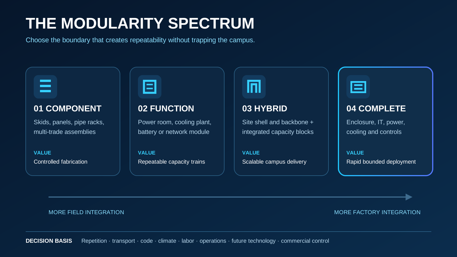
Define a capacity block that remains valid beyond one vendor generation
State whether the repeatable unit is an information-technology megawatt, a power train, a cooling train, a data hall, a cluster, or an integrated building block. Define usable information-technology load, power-usage-effectiveness basis, redundancy, rack-density range, cooling temperatures, residual air load, network and controls interfaces, fault containment, maintenance mode, and commissioning load. Size the block against credible demand and deployment cadence. A module optimized around one equipment generation can become stranded if later racks, voltages, coolant conditions, dimensions, or control protocols cannot be accommodated.
Modular Delivery Selection Matrix
| Approach | Factory scope | Strongest use | Primary dependency | Main exposure |
|---|---|---|---|---|
| Component modularization | Skids, panels, pipe racks and assemblies | Conventional projects seeking controlled fabrication | Coordinated connection points and repeat quantities | Local field integration remains extensive |
| Functional modules | Power rooms, cooling plants or battery systems | Repeatable capacity trains | Early one-lines, equipment and controls freeze | Transport, vendor interfaces and field connections |
| Hybrid facility | Site-built shell and backbone with modular infrastructure | Large scalable campuses | Strong owner reference design and interface governance | Split responsibility between shell, site and module suppliers |
| All-in-one facility | Enclosure, racks, power, cooling and controls | Remote, edge or rapid bounded deployments | Clear code path and stable capacity requirement | Vendor lock-in, limited expansion and replacement complexity |
This is a planning framework, not a universal ranking. Compare total installed cost, accepted capacity date, operating model, and portfolio reuse against a project-specific conventional baseline.
Design the permanent site backbone before arranging modules
The site must carry the systems that modules share: utility point of interconnection, substations, medium-voltage distribution, cooling production or heat-rejection headers, water and drainage, fiber entrances, controls network, roads, security, fire access, stormwater, grading, and future corridors. Map initial and ultimate capacity, loop or radial topology, isolation points, spare connections, hydraulic and electrical limits, maintenance access, and the sequence in which each backbone segment becomes live. The backbone should permit a new block to be set and commissioned without exposing operating capacity to uncontrolled construction work.
Freeze interfaces through Design for Manufacturing and Assembly
Factory work needs an approved interface-control document, not merely coordinated drawings. Define dimensions, weight, center of gravity, lifting points, temporary bracing, structural reactions, anchorage, utility connection coordinates, voltage, fault duty, pressure, flow, temperature, water quality, drainage, controls protocols, fire-alarm and suppression interfaces, weather seals, tolerances, access, and responsibility for each field joint. Use staged release gates so long-lead equipment can advance without treating every unresolved site condition as fixed. Assign authority for deviations and price the consequences of change after fabrication release.
Run factory and site work in parallel—but through common evidence gates
The modular schedule can shorten when site enabling work, foundations, utility backbone, and factory fabrication proceed concurrently from the same controlled basis. Each stream needs hold points: approved design inputs, released procurement, vendor submittals, field survey, embedded items, factory readiness, pre-shipment verification, receiving inspection, set completion, connections, startup, and integrated testing. Measure the date accepted capacity becomes available, not the date a module leaves the factory. Parallel work amplifies risk when field dimensions, utility conditions, software, or owner requirements continue to change independently.
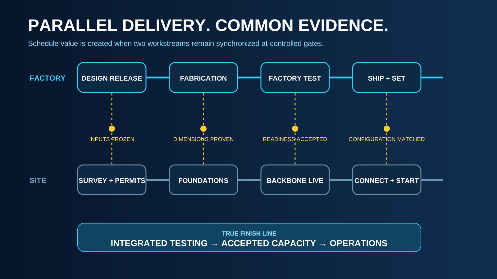
Treat transport, lifting, and setting as design inputs
Confirm module dimensions and weight, route geometry, bridge and pavement capacity, overhead clearance, permitting, police escort, seasonal restrictions, port or customs exposure, delivery windows, laydown, preservation, crane type, pick radius, ground bearing, wind limits, exclusion zones, temporary works, and recovery from a missed delivery. Coordinate module sequence with foundations, pipe and cable connections, roof or wall closure, fire access, and operating traffic. A factory-perfect module has no schedule value if it cannot reach the site, be safely lifted, or land within the cumulative tolerance of the receiving work.
Establish the code, fire, and permitting path before manufacturing release
Confirm how the authority classifies each assembly: equipment, listed package, relocatable structure, industrialized building component, or permanent building. Resolve occupancy, allowable area, fire separations, egress, structural design, wind and seismic demands, energy code, accessibility, fuel and battery provisions, suppression, detection, smoke control where applicable, exterior exposure, inspection access, third-party certification, and professional sealing. Factory inspection does not automatically replace local review. The approved design must trace which work is inspected at the factory, at receipt, after connection, and during final acceptance.
Commission the interfaces—not only the modules
Factory Acceptance Testing should verify the module against its approved functional and quality plan, but it cannot prove final utility behavior, field joints, site controls, installed hydraulics, environmental exposure, or campus failure sequences. Follow receiving inspection with Site Acceptance Testing, pre-functional checks, flushing and cleanliness verification, point-to-point controls tests, protection testing, load-bank or workload testing, integrated systems testing, and operational demonstrations. Preserve one deficiency and configuration record from factory through handover so a passed factory test cannot conceal an unresolved site dependency.
Factory-to-Operations Acceptance Chain
| Gate | Minimum evidence | What it releases | What it does not prove |
|---|---|---|---|
| Fabrication release | Approved design basis, interfaces, submittals and change authority | Controlled manufacturing and procurement | Final site readiness or installed performance |
| Factory Acceptance Test | Approved test plan, calibrated records, deficiencies and configuration | Shipment when contractual criteria are met | Utility, field-joint or campus failure performance |
| Receiving and set | Condition report, survey, anchorage, preservation and connections | Startup preparation | Functional capacity |
| Site Acceptance Test | Field checks, controls, protection, hydraulics and startup records | System-level commissioning | Integrated campus response |
| Integrated systems test | Normal and failure scenarios with accountable closure | Operational acceptance subject to qualifications | Future-phase compatibility without separate validation |
Plan operations, replacement, and multigeneration expansion
Show normal service access, consumables, coolant treatment, filters, battery and equipment replacement, roof and façade maintenance, spare strategy, isolation, temporary capacity, lifting, removal routes, and decommissioning. Decide whether the whole module, internal equipment, or selected components will be replaced. Protect future pads, utility taps, construction routes, and commissioning zones. Require configuration baselines and interface documentation that can support a later supplier or technology generation; otherwise rapid Phase 1 deployment may create a proprietary campus whose later phases are slower and more expensive.
Early screening checklist
What to verify before advancing this site.
- The modularity boundary and reason for selecting it are explicit
- The repeatable capacity block states usable load, density range, redundancy, cooling, controls, and test basis
- Permanent electrical, cooling, water, fiber, road, fire, security, and drainage backbones support every phase
- One interface-control document assigns geometry, loads, connections, tolerances, protocols, and ownership
- Release gates control changes while factory and site work proceed in parallel
- Transport route, module weight, permits, laydown, crane setup, ground bearing, and weather limits are proven
- The authority-approved code and inspection path covers factory, receipt, connection, and final acceptance
- Factory, site, and integrated testing share one configuration and deficiency record
- Operating access, isolation, replacement, removal, spares, and decommissioning are physically possible
- Future pads, utility taps, routes, and multivendor interface requirements are protected
What DCFR would flag
Risks surfaced at the screening stage.
DCFR would flag a modular concept that shows containers or skids without a permanent backbone, transport-and-lift proof, authority-approved code path, controlled interface document, integrated commissioning plan, or credible expansion and replacement strategy.
Professional confirmation required
Items requiring licensed validation.
Confirm capacity architecture, electrical and mechanical systems, controls, structural reactions, fire and life safety, listings, transport, lifting, foundations, commissioning, warranties, cost, schedule, and operations with the owner, manufacturers, licensed professionals, authorities, carriers, contractors, and commissioning provider.
Final takeaway
Modular delivery creates value when repeatable capacity, site backbone, factory work, field interfaces, testing, and future change are controlled as one system—not when conventional uncertainty is merely enclosed and shipped.
Screen up to 20 candidate sites before selecting one for the full DCFR report.
Each DCFR Report Package includes a preliminary 20-site comparison PDF / export package plus one selected planning-grade feasibility report.