
DCFR Insight 46 / AI Factories
AI Factory Planning for GPU Superclusters and Productive Compute
An AI factory is not a conventional data hall with denser racks. It is a synchronized system of accelerators, fabric, storage, power, liquid cooling, software, and operations whose real output is reliable computational work.
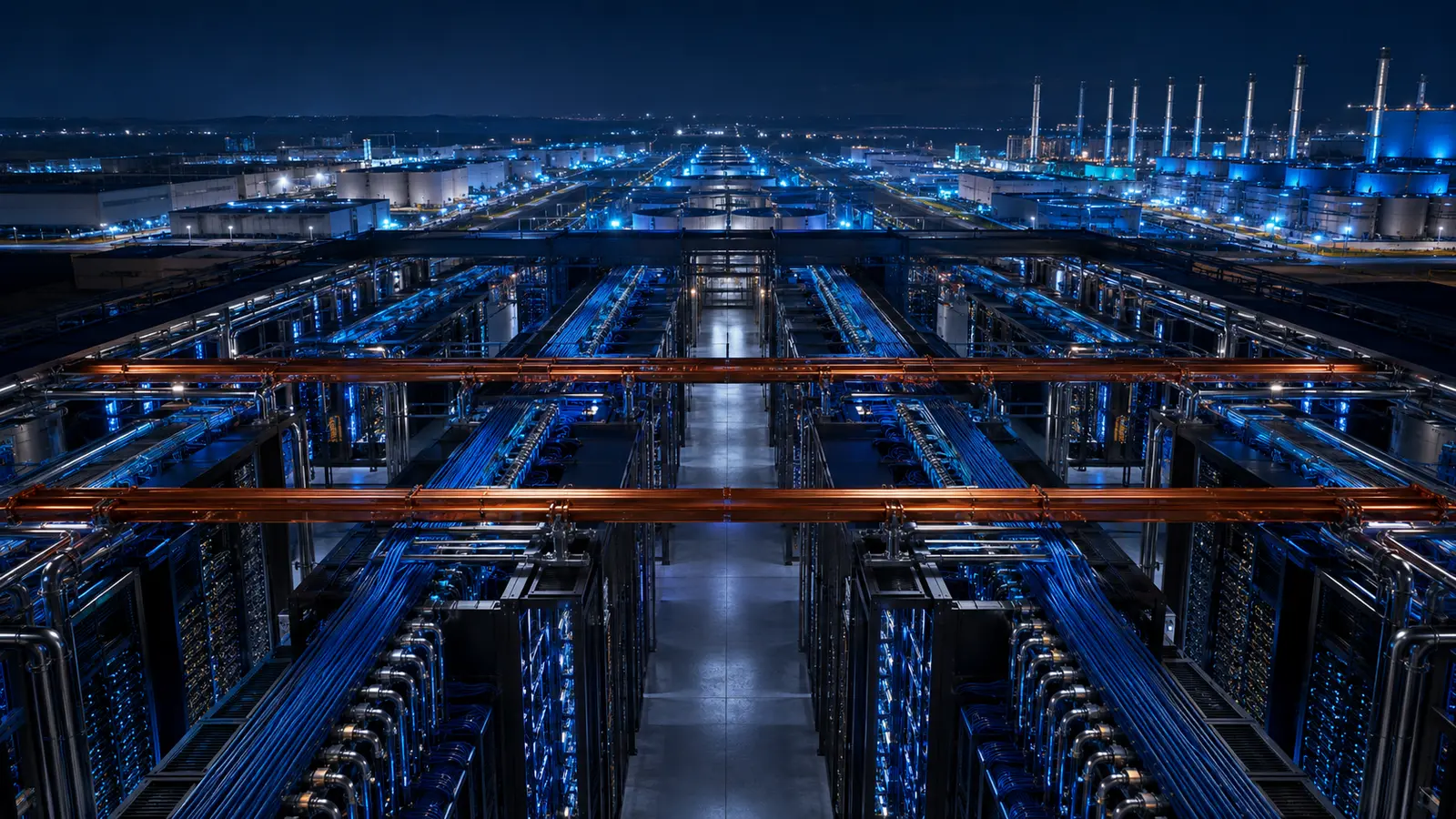
Define the product as completed work—not installed megawatts
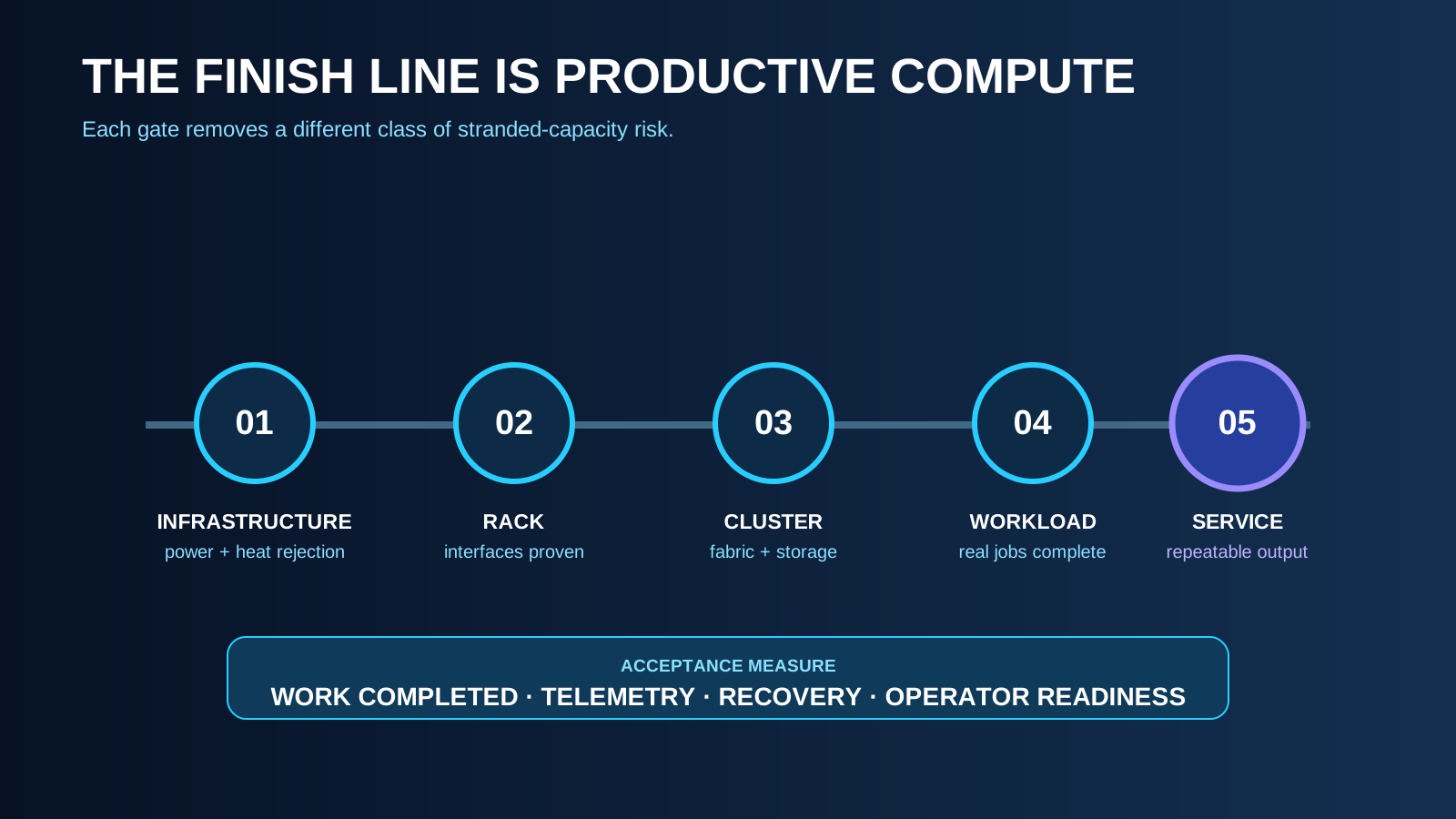
Start with the workload: training, inference, fine-tuning, simulation, or a mixed portfolio. State model scale, job duration, concurrency, data locality, latency, checkpoint behavior, availability, security, and growth assumptions. Translate these into accelerator count, cluster topology, network bandwidth, storage throughput, power profile, heat rejection, and recovery objectives. The core acceptance measure should be productive compute—workloads completed correctly and predictably—not only energized racks, nameplate accelerator quantity, or facility power capacity.
Treat the AI factory as one vertically integrated stack
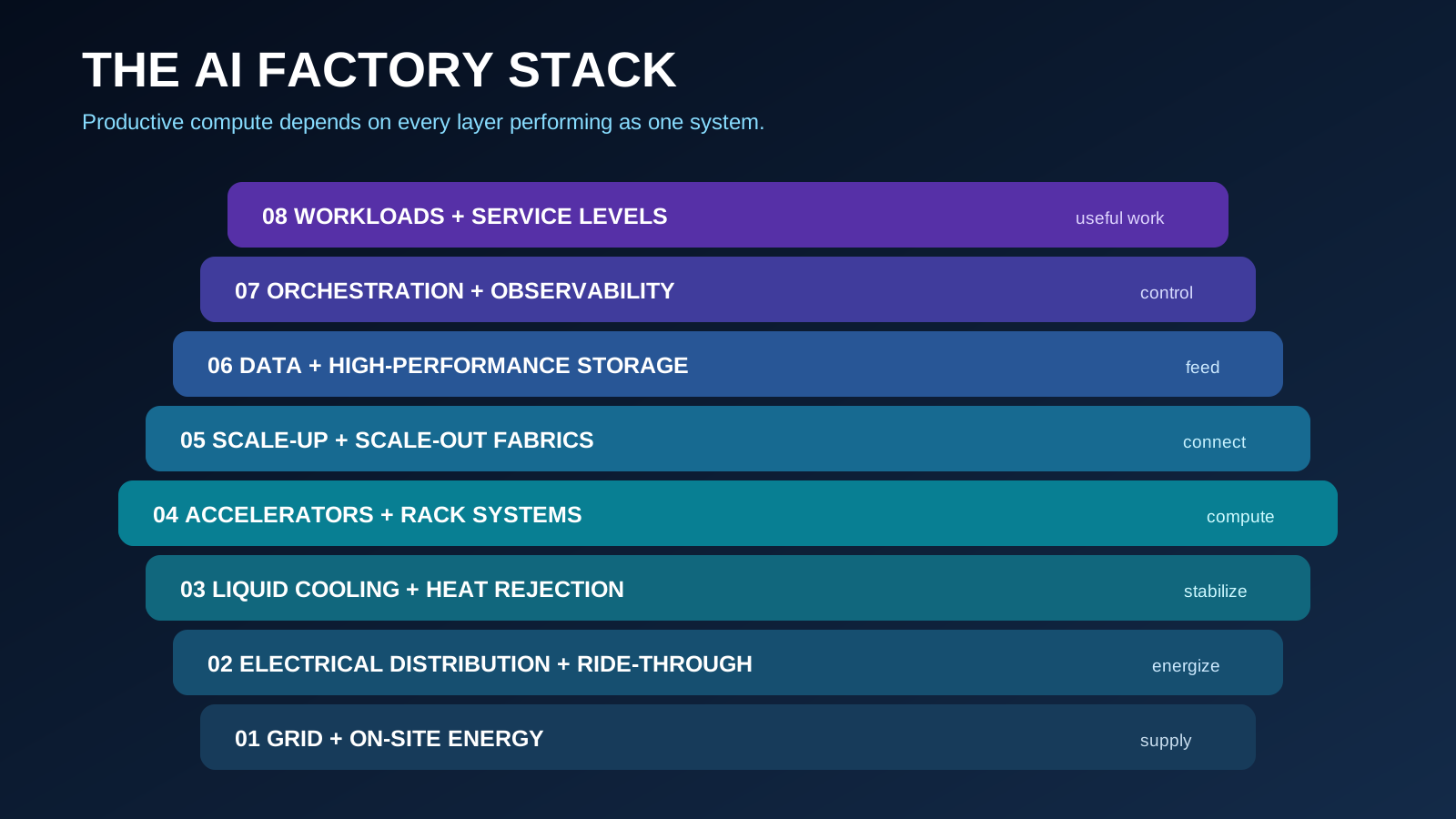
The system spans utility supply, generation and storage, medium-voltage distribution, rack power, heat capture, heat rejection, accelerators, scale-up and scale-out fabrics, storage, orchestration, observability, and workload software. Design teams need a shared model of dependencies and failure domains. A high-performance compute platform can be limited by weak storage, network oversubscription, unstable coolant temperatures, firmware drift, power-quality events, or job scheduling. Optimize total useful output and time to recovery across the stack rather than maximizing any single subsystem.
Lock the cluster topology before the building grid
Establish the smallest fault-contained compute unit and the largest job that must remain within a low-latency domain. Map rack arrangement, copper and optical reach, cable counts, rear-door or direct-liquid-cooling connections, overhead and underfloor zones, service clearances, replacement paths, and fabric expansion. The physical topology should follow the logical network and workload architecture. Reversing this sequence can force long cable routes, fragmented clusters, blocked service access, or a building bay that cannot accept the next platform generation.
AI Factory Basis of Design
| Layer | Design input | Acceptance evidence | Typical blind spot |
|---|---|---|---|
| Workload | Job types, size, concurrency and recovery | Representative jobs complete at agreed service level | Synthetic tests do not reflect production behavior |
| Compute and fabric | Cluster topology, fault domain and bandwidth | Health, performance and isolation tests | Logical design is forced into an unsuitable floor grid |
| Storage and data | Capacity, throughput, metadata and ingestion | End-to-end data path under load | Accelerators wait on storage or permissions |
| Power | Steady, transient, restart and maintenance states | Coordinated system response with rack emulation | Nameplate values replace time-based load behavior |
| Cooling | Heat split, temperatures, flow and water quality | Balanced clean system at all operating modes | Facility and IT ownership boundary is unresolved |
Requirements are platform- and workload-specific. Validate all values with current equipment suppliers and the owner’s operating model.
Engineer power for dynamic load and technology change
Model steady state, synchronized ramps, step loads, regenerative or harmonic behavior where applicable, restart sequences, maintenance states, and partial-cluster operation. Coordinate utility, on-site resources, transformers, protection, UPS architecture, busways, rack conversion, grounding, and controls against the actual platform. Preserve pathways for higher-voltage distribution and alternative rack-power architectures without assuming a future standard prematurely. Redundancy should align with job checkpointing and workload migration; identical facility tiers can produce very different business resilience.
Build a liquid-cooling operating system, not a pipe loop
Define facility-water and technology-cooling-system boundaries, supply temperatures, pressure, flow, water chemistry, materials compatibility, filtration, leak detection, make-up water, heat-exchanger approach, controls, flushing, cleanliness, sampling, and ownership. Validate behavior at minimum, normal, peak, transient, and maintenance conditions. Keep the residual air-cooling load explicit. Include connection standards and temporary cooling for technology replacement. The most dangerous ambiguity is often the interface between the facility operator and the information-technology equipment supplier.
Make data and network readiness a construction workstream
Accelerators are idle without validated fabrics, storage, software images, credentials, telemetry, and representative data. Coordinate diverse fiber entrances, carrier capacity, optical loss budgets, internal cabling, switch configuration, storage ingestion, cybersecurity, time synchronization, observability, and software release management with the physical build. Maintain an end-to-end readiness plan linking utility power, cooled racks, network domains, storage namespaces, orchestration, and user acceptance. This exposes dependencies that a traditional equipment-completion schedule misses.
Commission in layers until the workload proves the factory
Progress through component tests, factory tests, energized distribution, hydraulic cleaning and balancing, controls verification, rack emulation, network validation, platform health, and representative workloads. Test failures that cross domains: loss of a cooling distribution unit, fabric isolation, storage degradation, utility disturbance, generator transition, control-network interruption, leak response, and cluster restart. Record firmware, software, valve, protection, and control configurations at acceptance. Final demonstration should prove sustained workload performance, telemetry, recovery, and operating procedures—not a short synthetic peak alone.
Plan the campus as a sequence of technology cohorts
AI platforms may change faster than substations, buildings, and cooling plants. Group deployment into cohorts with known rack, voltage, coolant, fabric, and service assumptions. Protect backbone capacity and routes while allowing halls or modules to diverge. Decide which systems remain common and which can be replaced independently. Maintain a controlled reference design with an exceptions process, so speed comes from reuse while new hardware is admitted through evidence rather than forcing every phase into the first generation's constraints.
From Construction Complete to Productive Compute
| Gate | Question | Required proof |
|---|---|---|
| Infrastructure ready | Can the site safely energize and reject heat? | Protection, controls, hydraulic and failure-mode records |
| Rack ready | Are power, cooling and network interfaces within specification? | Measured interface conditions and configuration baseline |
| Cluster ready | Can the platform form, isolate and recover its domains? | Platform health, fabric, storage and recovery tests |
| Workload ready | Can real jobs run repeatably and observably? | Representative workload results and telemetry |
| Service accepted | Can operations sustain the promised outcome? | Procedures, spares, escalation, monitoring and owner sign-off |
Operate around failure domains and computational service levels
Create a responsibility model spanning facilities, network, platform, storage, security, and workload operations. Correlate electrical, thermal, hardware, fabric, and job telemetry on a shared timeline. Define isolation, degraded modes, checkpoint policy, spares, break-fix access, liquid-cooling response, and return-to-service gates. Measure job completion, utilization quality, failed-work loss, recovery time, energy per useful unit of computation, and change reliability. Facility availability alone can look healthy while productive compute is impaired.
Early screening checklist
What to verify before advancing this site.
- The workload model defines productive compute and recovery objectives
- Logical cluster and fault-domain topology drives the physical layout
- Power studies include ramps, steps, restart, maintenance, and degraded states
- Liquid-cooling interfaces assign chemistry, cleanliness, controls, and ownership
- Residual air load and every heat-rejection mode are quantified
- Network, storage, software, security, and data readiness are on the master schedule
- Commissioning progresses from components to representative workloads
- Cross-domain failures and return-to-service sequences are demonstrated
- Technology cohorts can change without rebuilding the permanent backbone
- Operations correlate facility, platform, fabric, storage, and job telemetry
What DCFR would flag
Risks surfaced at the screening stage.
DCFR would flag an AI factory defined primarily by accelerator count or facility megawatts without a workload model, topology-driven layout, liquid-cooling interface standard, dynamic power study, data-and-network readiness path, or productive-compute acceptance test.
Professional confirmation required
Items requiring licensed validation.
Confirm workloads, platform topology, power characteristics, coolant requirements, network and storage performance, software, security, commissioning, service levels, and operating responsibilities with current manufacturers, the owner, utilities, licensed professionals, integrators, contractors, and authorities.
Final takeaway
An AI factory is complete only when infrastructure, platform, data, software, and operations repeatedly convert energy into useful computational work.
Screen up to 20 candidate sites before selecting one for the full DCFR report.
Each DCFR Report Package includes a preliminary 20-site comparison PDF / export package plus one selected planning-grade feasibility report.