
DCFR Insight 21 / Land + Water Efficiency
Sustainable CapacityResource-Efficient Data Center Campuses: More Compute with Less Land and Water
Data center efficiency is not only an energy question. The next generation of campuses must deliver more usable compute per developable acre while reducing freshwater dependency—without compromising resilience, fire access, maintainability, heat rejection, construction logistics, or future expansion.
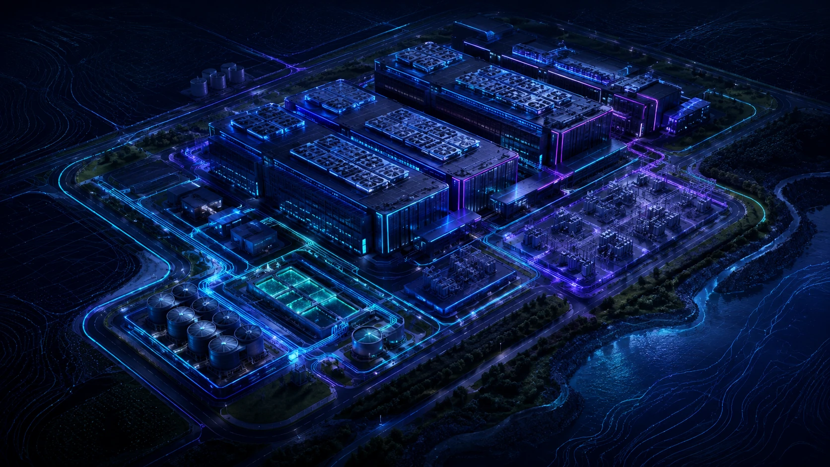
Data center efficiency extends beyond PUE
The objective is not to create the smallest possible building or claim zero water use. It is to maximize responsible compute capacity per constrained acre and minimize freshwater dependence across the complete infrastructure system. PUE describes only part of that system. Planning must relate usable IT capacity to net developable land, onsite water volume and source, indirect water associated with electricity, and the method by which captured heat finally leaves the site. It must also preserve resilience, maintainability, appropriate infrastructure duplication, and future adaptability. A lower onsite water figure or smaller footprint is not a success if it creates an unmaintainable plant, an unacceptable failure domain, or resource demand outside the stated measurement boundary.
Measure capacity against net developable land—not gross acreage
Gross acreage is not net developable acreage. Map and deduct setbacks, buffers, wetlands, floodplain, slopes, easements, stormwater facilities, substations, transmission corridors, generator yards, fuel systems, cooling equipment, fire lanes, security zones, parking, construction logistics, replacement routes, and unusable remnants. Some areas remain part of the owned parcel but cannot carry productive capacity; others support capacity and should be classified transparently rather than hidden. Compare scenarios on the same boundary and preserve access and environmental constraints. Gross-acreage claims can overstate usable capacity when the denominator includes undevelopable land or when essential utility and water infrastructure is omitted from the campus area.
Define what “more compute” means
Utility MW is not necessarily usable IT MW. Distinguish utility service capacity, facility input MW, IT MW, critical IT MW under the required redundancy state, usable rack capacity at supported densities, commissioned capacity, occupied capacity, and reserved future capacity. State whether the numerator reflects nameplate, contracted, energized, tested, or customer-deployable capacity and identify coincident loads and operating limits. Rack density alone also says little without rack count, cooling support, network and power distribution, and workload utilization. Nominal megawatts do not establish productive land use. Metrics such as MW per developable acre or acres per MW are comparative scenario tools only; no universal target applies across different climates, utilities, programs, redundancy bases, or site constraints.
Higher rack density can reduce building demand—but shifts infrastructure
Higher rack density can mean fewer racks and data halls for the same compute, but saved white-space area shifts intensity. Electrical distribution becomes denser; structural loads concentrate; liquid-cooling distribution, CDU locations, piping, controls, maintenance zones, and heat-rejection equipment grow in importance. Redundancy and commissioning must address larger failure concentrations and the consequences of a branch or CDU outage. Compare scenarios at the complete system boundary, including electrical rooms, support plant, pipe corridors, service clearances, replacement paths, and test space. Density creates value when compute and supporting infrastructure are jointly optimized, not when a smaller building plan exports unresolved equipment and access demand to the yard or roof.
Liquid cooling does not automatically mean low water use
‘Liquid-cooled’ describes how heat is captured. It does not, by itself, describe how heat ultimately leaves the site. Direct-to-chip systems and immersion systems where applicable transfer IT heat into facility-water loops through CDUs or heat exchangers. Those closed internal loops may retain their fluid, while chilled-water loops, dry coolers, evaporative towers, or hybrid systems perform final rejection. Heat reuse can displace some rejection only when a reliable sink, temperature match, controls, commercial arrangement, and backup rejection path exist; residual heat still requires a design basis. Consumptive water therefore depends on final heat rejection, treatment, blowdown, climate, and operating mode—not the coolant adjacent to the processor.
Compare dry, evaporative, and hybrid heat rejection honestly
Dry heat rejection can reduce onsite water dependency, but may require more equipment area, fan energy, acoustic control, and higher approach temperatures, with high-ambient limitations or capacity derating. Evaporative rejection consumes water and requires treatment, blowdown, drift and plume control, maintenance, and reliable water quality, yet may reduce heat-rejection energy in suitable conditions. Hybrid systems select dry and wet modes seasonally or by load and weather, potentially reducing annual water while retaining peak capability, but add controls, maintenance, and commissioning complexity. No system is universally best. Compare peak-day capacity, annual energy and water, source reliability, failure operation, footprint, noise, treatment, discharge, maintenance skill, and lifecycle implications under site-specific conditions.
Let climate, watershed, and utility conditions control the strategy
Use coincident dry-bulb and wet-bulb conditions, annual bins, drought scenarios, watershed stress, water rights, potable and reclaimed supply, sewer capacity, discharge restrictions, freeze, dust, corrosion, and humidity. Add electricity carbon intensity and grid water intensity, including seasonal availability where credible data exists. Water allocation that is adequate annually may fail on a peak day or during drought; reclaimed water may have outages, variable chemistry, or competing demand. A dry system may avoid onsite consumption but increase peak electrical demand at the grid's most constrained hour. Identical cooling architecture should not be copied indiscriminately between regions because climate, watershed, utility, water-source, and sewer constraints determine different responsible trade-offs.
Consolidate infrastructure without creating common-mode failure
Shared utility yards, centralized cooling and treatment, consolidated substations, shared pipe corridors, and common controls can reduce duplicated land and equipment. Consolidation must still define failure domains, phased redundancy, physical and controls isolation, maintainability, bypass, and replacement access. A shared header, treatment train, controls network, trench, or access route should not allow one leak, fault, maintenance event, cyber or controls failure, or construction incident to disable the campus. Model capacity through each development phase, since an ultimate redundant plant may be under-redundant early. The objective is purposeful sharing with testable isolation—not either maximum duplication or concentration without consequence analysis.
Use vertical space strategically
Multi-level data halls, stacked support areas, and rooftop equipment may improve land utilization where structure, code, and operations support them. Evaluate concentrated structural loads, vibration, egress, fire-department access, replacement and lifting routes, roof penetrations, waterproofing, maintenance safety, and phased expansion. Rooftop equipment can free yard area but complicate crane access, acoustic treatment, leak management, structural reinforcement, and replacement during live operation. Vertical development can also increase construction sequence and material demand. It should be compared with horizontal options using the same capacity, resilience, maintenance, and expansion boundary; it is not a universal recommendation for every soil condition, seismic regime, fire strategy, or operating model.
Right-size parking, roads, support buildings, and temporary facilities
Separate permanent staffing from construction peaks. Test shared parking, shift management, temporary parking, remote staging, and future conversion before paving for peak construction demand. Size roads for verified vehicles, turning movements, emergency access, security, deliveries, equipment replacement, snow or storm operations, and phased circulation—not arbitrary uniform widths. Temporary offices, laydown, warehousing, and contractor facilities need planned locations and restoration or conversion dates. Temporary construction demand should not automatically become permanent paved area, but compactness cannot compromise apparatus access, safe pedestrian routes, queuing, lifting, or replacement. The plan should show how logistics change between construction phases and steady operation.
Treat stormwater as primary infrastructure
Stormwater cannot be placed only on leftover land. Impervious area, detention, water quality, infiltration feasibility, flood routing, grading, downstream discharge limits, and maintenance access shape developable capacity from the first plan. Evaluate rainwater capture and reuse for cooling makeup where permitted, irrigation, or other nonpotable demand, while separating fire-water reliability and confirming treatment, storage, seasonal yield, and overflow. Capture claims should use realistic rainfall and demand timing rather than tank volume alone. Protect major drainage paths and future climate resilience so densification does not increase off-site risk or flood critical equipment. The stormwater reserve belongs in every land-efficiency denominator.
Define future expansion precisely
Distinguish reserved land, contracted or reserved utility capacity, substation positions, cooling capacity, water allocation, protected utility routes, future building pads, swing space, and replacement space. Each reserve should have a purpose, activation condition, infrastructure dependency, and expiry or review trigger. A pad without a protected power route, drainage strategy, construction access, and heat-rejection allowance is not credible expansion. Replacement space is not necessarily growth capacity; it may be essential to maintain live equipment. Undefined excess land can conceal inefficient planning, while premature buildout can strand capital and resources. Scenario plans should show both interim and ultimate configurations without blocking the routes required to reach them.
Reduce potable-water dependence before claiming water efficiency
Use a disciplined sequence: reduce heat load; improve IT utilization and efficiency; improve cooling efficiency; optimize control temperatures; select appropriate final heat rejection; recover or reuse water where technically suitable; evaluate reclaimed or nonpotable supply; reduce blowdown where applicable; capture condensate or rainwater where viable; verify water quality; and establish treatment and operational planning. Quantify annual and peak-day demand, drought and outage operation, storage, chemistry, health controls, discharge, and operator needs. No source or system is universally appropriate. Potable-water substitution that adds unreliable treatment or unacceptable corrosion is not resilient, while efficient evaporative operation may still be unsuitable where watershed or allocation conditions are constrained.
Measure direct and indirect resource effects
Define boundaries for onsite water and WUE, indirect water associated with electricity, energy, land, materials, backup generation, infrastructure duplication, and heat reuse. Onsite WUE does not represent all indirect water used in electricity production, and grid averages may not describe marginal or seasonal effects. Compare both peak design conditions and annual operating conditions: peak sizing governs capacity and land, while annual simulation informs consumption. Include construction and replacement implications where they materially distinguish options. A single metric can transfer impact elsewhere—for example, dry rejection may reduce onsite water while increasing equipment, fan energy, and peak power. Planning metrics are comparative scenario tools, not universal performance promises.
Avoid transferring impact from one constrained resource to another
Test resource transfers explicitly: saving water while increasing peak electrical demand; increasing density while reducing maintainability; reducing roads while compromising fire access; consolidating cooling while creating common-mode risk; reducing building area while increasing structural or mechanical complexity; reserving expansion land without protecting utility routes; or reducing onsite water while using water-intensive electricity. Lower onsite water use does not automatically mean lower total environmental impact. Establish minimum resilience, fire access, replacement access, maintainability, code, and operational criteria before optimizing. Then compare the remaining options with transparent boundaries and sensitivity cases. Optimization is a multi-constraint decision, not a contest to minimize one visible number.
Create a resource-efficiency decision record
For each major choice, record scenarios, assumptions, climate data, water source, land deductions, cooling basis, final heat-rejection basis, redundancy, peak and annual performance, cost, schedule, and operational requirements. Name the professional confirmation owner, decision authority, rationale, evidence date, and future revision triggers such as utility changes, water restrictions, equipment density, climate updates, or expansion. Preserve rejected options and sensitivities so later teams understand why a strategy fit this site. The record should identify metric boundaries and uncertainty, avoiding universal WUE or land-density claims. Revisit it at design gates and after measured operation so the reference design learns from verified outcomes rather than slogans.
Land + Water Optimization Trade-Off Matrix
| Strategy | Potential land effect | Potential water effect | Primary benefit | Primary risk or trade-off |
|---|---|---|---|---|
| Higher rack density | May consolidate area or shift support footprint | Depends on final rejection and source | Scenario-specific reduction in constrained resource | Complexity, reliability, access or transferred impact |
| Multi-level data hall | May consolidate area or shift support footprint | Depends on final rejection and source | Scenario-specific reduction in constrained resource | Complexity, reliability, access or transferred impact |
| Centralized utility yard | May consolidate area or shift support footprint | Depends on final rejection and source | Scenario-specific reduction in constrained resource | Complexity, reliability, access or transferred impact |
| Shared cooling plant | May consolidate area or shift support footprint | Depends on final rejection and source | Scenario-specific reduction in constrained resource | Complexity, reliability, access or transferred impact |
| Dry heat rejection | May consolidate area or shift support footprint | Depends on final rejection and source | Scenario-specific reduction in constrained resource | Complexity, reliability, access or transferred impact |
| Evaporative heat rejection | May consolidate area or shift support footprint | Depends on final rejection and source | Scenario-specific reduction in constrained resource | Complexity, reliability, access or transferred impact |
| Hybrid heat rejection | May consolidate area or shift support footprint | Depends on final rejection and source | Scenario-specific reduction in constrained resource | Complexity, reliability, access or transferred impact |
| Direct liquid cooling | May consolidate area or shift support footprint | Depends on final rejection and source | Scenario-specific reduction in constrained resource | Complexity, reliability, access or transferred impact |
| Reclaimed-water supply | May consolidate area or shift support footprint | Depends on final rejection and source | Scenario-specific reduction in constrained resource | Complexity, reliability, access or transferred impact |
| Rainwater or condensate reuse | May consolidate area or shift support footprint | Depends on final rejection and source | Scenario-specific reduction in constrained resource | Complexity, reliability, access or transferred impact |
| Consolidated parking | May consolidate area or shift support footprint | Depends on final rejection and source | Scenario-specific reduction in constrained resource | Complexity, reliability, access or transferred impact |
| Temporary construction parking | May consolidate area or shift support footprint | Depends on final rejection and source | Scenario-specific reduction in constrained resource | Complexity, reliability, access or transferred impact |
| Rooftop equipment | May consolidate area or shift support footprint | Depends on final rejection and source | Scenario-specific reduction in constrained resource | Complexity, reliability, access or transferred impact |
| Reserved future pad | May consolidate area or shift support footprint | Depends on final rejection and source | Scenario-specific reduction in constrained resource | Complexity, reliability, access or transferred impact |
| Shared utility corridor | May consolidate area or shift support footprint | Depends on final rejection and source | Scenario-specific reduction in constrained resource | Complexity, reliability, access or transferred impact |
Resource-Efficiency Decision Framework
| Decision | Required planning evidence | Professional confirmation | DCFR concern |
|---|---|---|---|
| Net developable acreage | Mapped boundary, calculations, scenarios and constraints | Relevant A/E, provider, owner and authority | Undefined boundary, unsupported supply or transferred risk |
| Compute-capacity basis | Mapped boundary, calculations, scenarios and constraints | Relevant A/E, provider, owner and authority | Undefined boundary, unsupported supply or transferred risk |
| Rack-density scenario | Mapped boundary, calculations, scenarios and constraints | Relevant A/E, provider, owner and authority | Undefined boundary, unsupported supply or transferred risk |
| Cooling architecture | Mapped boundary, calculations, scenarios and constraints | Relevant A/E, provider, owner and authority | Undefined boundary, unsupported supply or transferred risk |
| Final heat rejection | Mapped boundary, calculations, scenarios and constraints | Relevant A/E, provider, owner and authority | Undefined boundary, unsupported supply or transferred risk |
| Water source | Mapped boundary, calculations, scenarios and constraints | Relevant A/E, provider, owner and authority | Undefined boundary, unsupported supply or transferred risk |
| Annual water demand | Mapped boundary, calculations, scenarios and constraints | Relevant A/E, provider, owner and authority | Undefined boundary, unsupported supply or transferred risk |
| Peak-day water demand | Mapped boundary, calculations, scenarios and constraints | Relevant A/E, provider, owner and authority | Undefined boundary, unsupported supply or transferred risk |
| Reclaimed-water availability | Mapped boundary, calculations, scenarios and constraints | Relevant A/E, provider, owner and authority | Undefined boundary, unsupported supply or transferred risk |
| Sewer and blowdown | Mapped boundary, calculations, scenarios and constraints | Relevant A/E, provider, owner and authority | Undefined boundary, unsupported supply or transferred risk |
| Stormwater reserve | Mapped boundary, calculations, scenarios and constraints | Relevant A/E, provider, owner and authority | Undefined boundary, unsupported supply or transferred risk |
| Shared infrastructure | Mapped boundary, calculations, scenarios and constraints | Relevant A/E, provider, owner and authority | Undefined boundary, unsupported supply or transferred risk |
| Future expansion | Mapped boundary, calculations, scenarios and constraints | Relevant A/E, provider, owner and authority | Undefined boundary, unsupported supply or transferred risk |
| Replacement access | Mapped boundary, calculations, scenarios and constraints | Relevant A/E, provider, owner and authority | Undefined boundary, unsupported supply or transferred risk |
| Fire and emergency access | Mapped boundary, calculations, scenarios and constraints | Relevant A/E, provider, owner and authority | Undefined boundary, unsupported supply or transferred risk |
| Indirect water and energy effects | Mapped boundary, calculations, scenarios and constraints | Relevant A/E, provider, owner and authority | Undefined boundary, unsupported supply or transferred risk |
Cooling and Heat-Rejection Comparison
| System | Onsite water dependency | Land and equipment effect | Energy and climate consideration | Key confirmation item |
|---|---|---|---|---|
| Air-cooled IT with dry heat rejection | Low to material depending on system and operating mode | Verify complete plant footprint and access | Model peak and annual site climate; no universal ranking | Final rejection capacity, source reliability and failure mode |
| Air-cooled IT with evaporative rejection | Low to material depending on system and operating mode | Verify complete plant footprint and access | Model peak and annual site climate; no universal ranking | Final rejection capacity, source reliability and failure mode |
| Direct liquid cooling with dry rejection | Low to material depending on system and operating mode | Verify complete plant footprint and access | Model peak and annual site climate; no universal ranking | Final rejection capacity, source reliability and failure mode |
| Direct liquid cooling with evaporative rejection | Low to material depending on system and operating mode | Verify complete plant footprint and access | Model peak and annual site climate; no universal ranking | Final rejection capacity, source reliability and failure mode |
| Direct liquid cooling with hybrid rejection | Low to material depending on system and operating mode | Verify complete plant footprint and access | Model peak and annual site climate; no universal ranking | Final rejection capacity, source reliability and failure mode |
| Heat-recovery system with residual dry rejection | Low to material depending on system and operating mode | Verify complete plant footprint and access | Model peak and annual site climate; no universal ranking | Final rejection capacity, source reliability and failure mode |
| Heat-recovery system with residual evaporative rejection | Low to material depending on system and operating mode | Verify complete plant footprint and access | Model peak and annual site climate; no universal ranking | Final rejection capacity, source reliability and failure mode |
Capacity-delivery review checklist
What to verify before the next release gate.
- Gross and net developable acreage separated
- All land deductions mapped
- Capacity basis defined as utility, facility, IT and commissioned capacity
- Rack-density scenarios compared
- Structural implications reviewed
- Cooling architecture defined
- Final heat-rejection method identified
- Direct and indirect water boundaries stated
- Onsite WUE boundary stated
- Annual and peak-day water demand estimated
- Climate design conditions confirmed
- Watershed and drought context reviewed
- Water rights and allocation reviewed
- Potable and nonpotable sources assessed
- Reclaimed-water reliability reviewed
- Water-quality and treatment requirements reviewed
- Sewer and blowdown conditions reviewed
- Dry, evaporative and hybrid scenarios compared
- Cooling acoustic effects reviewed
- Common-mode failure risks reviewed
- Shared-infrastructure isolation established
- Permanent and temporary parking demand separated
- Construction logistics planned
- Fire lanes and apparatus access protected
- Replacement routes protected
- Stormwater reserve established
- Flood routing reviewed
- Future expansion precisely defined
- Utility corridors protected
- Peak and annual energy impacts compared
- Resource transfers documented
- Professional confirmations assigned
- Decision rationale recorded
What DCFR would flag
Delivery risks that should be visible early.
DCFR would flag oversized low-density buildings, duplicated utility infrastructure, permanent parking based on temporary construction peaks, undefined expansion reserves, land-efficiency claims based on gross rather than developable acreage, potable-water-dependent cooling in water-stressed locations, and claims of ‘water-free liquid cooling’ that do not identify the final heat-rejection system.
Professional confirmation required
Items requiring project-specific validation.
Final site capacity, rack density, cooling architecture, heat-rejection system, water demand, water source, utility service, stormwater design, structural system, equipment arrangement, environmental impact, code compliance, cost, schedule, and operational resilience require confirmation by the owner, IT equipment providers, Architect and Engineers of Record, utility providers, manufacturers, operators, environmental consultants, water and sewer providers, and Authorities Having Jurisdiction.
Final takeaway
The most resource-efficient data center is not simply the smallest building or the lowest onsite water user. It is the campus that delivers the required compute with the least constrained land and freshwater demand while preserving resilience, maintainability, environmental compatibility, and future adaptability.
Surface site, code, utility, and delivery risk before it becomes expensive.
DCFR converts early assumptions into planning-grade flags, confirmation registers, and decision-ready feasibility outputs.