
DCFR Insight 30 / Data Center Delivery + Design Governance
Basis of Design + Reference DesignStandardizing Data Centers from Basis of Design to Reference Design
A repeatable data center program needs more than a prototype drawing set. It needs a controlled chain from owner requirements and Basis of Design to reference design, site adaptation, deviation approval, commissioning, and lessons learned.

Start Before the Basis of Design: Define the Owner's Project Requirements
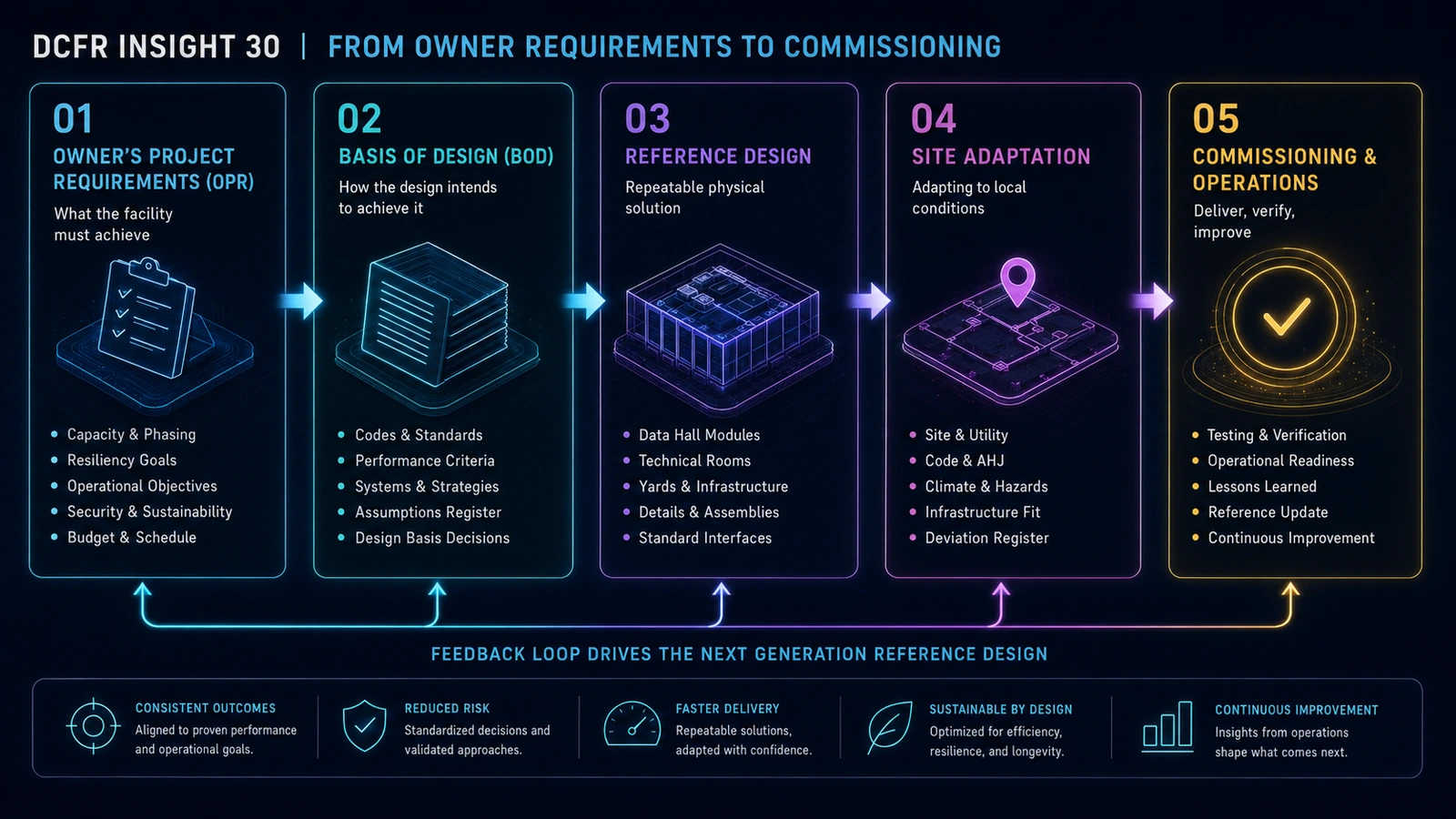
A repeatable data center is not created by copying drawings. Successful multi-site programs standardize aggressively without pretending every site is identical. Climate, utility service, flood, wind, seismic, hail, wildfire, groundwater, geotechnical conditions, local adoption, Authority Having Jurisdiction (AHJ) interpretations, insurer criteria, water availability, equipment, and rack density all change. The useful question is: what must remain constant to protect performance, and what must be revalidated for every site? That distinction is the foundation of a useful Basis of Design (BOD). A strong control system begins with the Owner's Project Requirements (OPR): what the facility must accomplish. Record target Information Technology (IT) capacity, resilience, phasing, operations, maintainability, sustainability, security, schedule, technology flexibility, budget, and commissioning expectations. Owner's Project Requirements (OPR) ↓ Basis of Design (BOD) ↓ Reference Design ↓ Site-Specific Adaptation ↓ Construction Documents ↓ Commissioning + Operations Feedback ↓ Updated Reference Design
- 1
Owner's Project Requirements
What must the facility accomplish?
- 2
Basis of Design
How will the design achieve those requirements, and which criteria and assumptions govern?
- 3
Reference Design
What repeatable physical solution expresses that design basis?
- 4
Site-Specific Package
What changes because of the parcel, jurisdiction, utility, climate, equipment, insurer, construction market, or owner decision?
STANDARDIZE PERFORMANCE INTENT; REVALIDATE SITE CONDITIONS.
A Basis of Design Should Be a Decision Document, Not a Project Description
A weak Basis of Design describes the proposed building. A strong Basis of Design records the decisions that control it. The following twelve groups form a working decision register, with every value tagged as code or standard basis, manufacturer requirement, engineering requirement, owner standard, DCFR planning assumption, or project confirmation required.
- 1
01 — Capacity + technology basis
Define target Information Technology load, initial phase and ultimate campus capacity, rack-count estimate, initial average density, initial maximum density, future maximum design density, Artificial Intelligence (AI) or high-density percentage, module capacity, rack electrical architecture, and future allowance. One average density cannot control the future building.
- 2
02 — Data hall module
Define megawatts and rack range per module, row organization, hot-aisle and cold-aisle strategy, containment, liquid readiness, power and network interfaces, expansion logic, and fire-protection interfaces. Standardize a module—not an undifferentiated white-space rectangle.
- 3
03 — Electrical architecture
Define architectural interfaces for utility service, transformers, switchgear, Uninterruptible Power Supply (UPS), batteries, generators, segregation, maintenance bypass, and replacement. Electrical calculations belong to the responsible engineer; architecture must preserve space, access, separation, structure, rated construction, maintenance, and replacement conditions.
- 4
04 — Cooling architecture
Name the technology envelope: direct expansion, chilled water, air-cooled plant, direct-to-chip liquid, rear-door heat exchangers, liquid-to-air or liquid-to-liquid Coolant Distribution Units (CDUs), or a controlled hybrid. Approximately 120 kilowatts per rack is used here only as a current technology reference example—not a code requirement or universal default.
- 5
05 — Architecture + envelope
Define typology, hall organization, wall and roof performance, water, thermal, air and vapor control, durability, climate response, penetration and fire-resistance continuity, screening, roof access, and major replacement openings. The Basis of Design defines performance; the reference design establishes approved assemblies.
- 6
06 — Fire + life safety
Define occupancy assumptions, construction type, resistance, compartments, penetrations, detection, suppression, battery strategy, egress, apparatus access, fire water, and insurer criteria. The 2024 International Building Code (IBC) and 2024 International Fire Code (IFC) are current model-code reference bases; verify the edition and amendments adopted by the project jurisdiction.
- 7
07 — Site + campus
Standardize site-planning logic—not one plan. Define building placement, utility edge, people and truck access, fire and security access, technical yards, loading, stormwater, laydown, replacement, and expansion reserve.
- 8
08 — Structure
Record planning criteria for grid, technical equipment, racks, batteries, roof plant, vibration-sensitive areas, openings, replacement paths, and future flexibility. Final values are an engineering requirement established by the structural Engineer of Record (EOR).
- 9
09 — Security
Use PUBLIC → CONTROLLED → RESTRICTED → CRITICAL zoning and coordinate visitors, employees, trucks, contractors, loading, technical yards, roof, emergency access, and replacement routes.
- 10
10 — Maintainability + replacement
For transformers, switchgear, UPS equipment, batteries, generators, pumps, heat exchangers, CDUs, chillers, air handlers, and heat rejection, ask: Can it enter? Operate? Be maintained? Can a major component be withdrawn? Can the complete unit be replaced?
- 11
11 — Energy + sustainability
Record energy-standard basis, water and heat-rejection strategy, low-carbon objectives, renewable readiness, reuse, heat recovery, storage, and climate-specific envelope response. Use American Society of Heating, Refrigerating and Air-Conditioning Engineers (ASHRAE) ANSI/ASHRAE Standard 90.4-2025, Energy Standard for Data Centers, where applicable and confirm adopted or contractual criteria for the project.
- 12
12 — Commissioning + operations
Define verification of electrical systems, cooling, controls, alarms, leak detection, fire protection, failover, isolation, maintainability, procedures, training, and documentation. A package that has not survived construction, testing, commissioning, and operation is not automatically a mature standard.
Create a Design Basis Register
Give each controlling requirement a source, classification, confirmation owner, and status. This prevents an early feasibility value from silently becoming a contractual or regulatory requirement. The example below separates owner decisions, local criteria, engineering work, manufacturer data, and planning assumptions.
Example Design Basis Register
| Requirement | Design Basis | Classification | Source | Confirmation |
|---|---|---|---|---|
| Information Technology capacity | 40 megawatts | Locked | Owner | Approved |
| Initial rack assumption | 40 kilowatts per rack | DCFR Planning Assumption | Early feasibility | Confirm tenant |
| Future technology class | High-density / liquid-ready | Locked / Parametric | Owner | Confirm |
| Building code | 2024 International Building Code reference basis | Local | International Code Council | Verify adopted edition |
| Fire code | 2024 International Fire Code reference basis | Local | International Code Council | Verify adopted edition |
| Electrical requirements | National Electrical Code | Local / Engineering | National Fire Protection Association | Verify adopted edition |
| Data center energy | ANSI/ASHRAE Standard 90.4-2025 | Local / Owner | American Society of Heating, Refrigerating and Air-Conditioning Engineers | Verify applicability |
| Battery systems | Project-specific stationary energy-storage basis | Local / Engineering | National Fire Protection Association / Engineer | Confirm configuration |
| Roof / envelope | Owner + insurer performance criteria | Parametric | Owner / insurer | Confirm site |
| Equipment clearances | Manufacturer-specific | Parametric | Selected vendor | Confirm equipment |
The 40-megawatt and 40-kilowatt values are example owner and DCFR planning inputs respectively, not code or universal design criteria.
Every Requirement Should Be Classified
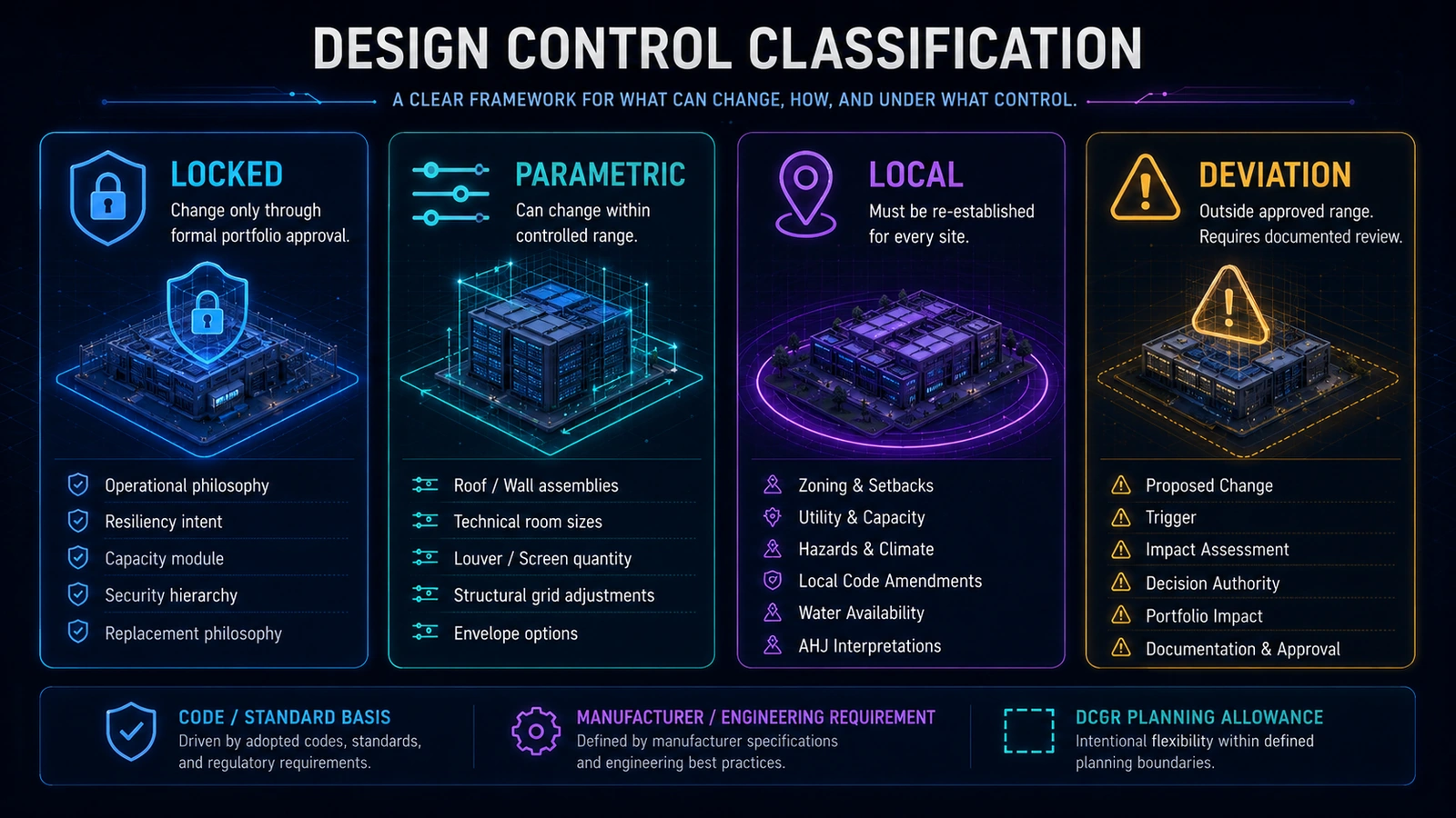
Classification determines who may change a decision and what evidence is required. Locked items change only through formal portfolio approval. Parametric items can move inside an approved, documented range. Local items must be re-established at every site. A deviation sits outside that range and requires documented technical and owner review.
- 1
LOCKED
Operational philosophy; resilience intent; capacity module; security hierarchy; major interfaces; equipment-replacement philosophy.
- 2
PARAMETRIC
Insulation and roof or wall assemblies; technical-room dimensions; cooling-module or louver quantity; structural-grid adjustments; acoustic screening.
- 3
LOCAL
Zoning, setbacks, utility capacity and voltage, flood, wind, seismic, snow, rainfall, groundwater, geotechnical conditions, water availability, AHJ interpretation, and insurer requirements.
- 4
DEVIATION
A condition outside the approved reference range. Record the trigger, technical consequences, reviewers, owner decision, and whether it is site-only, a controlled variant, or a reference-design update.
Dimensions Need Governance Too
Every reference-design dimension needs an identifiable basis. CODE / STANDARD BASIS: under the 2024 International Building Code reference basis, an applicable means-of-egress door opening generally requires 32 inches minimum clear width and 80 inches minimum clear height. Verify the adopted edition, amendments, occupancy conditions, and exceptions. A 32-inch code-compliant personnel door is not automatically an adequate equipment-replacement opening. MANUFACTURER REQUIREMENT: shipping dimensions, chiller tube pull, battery service area, switchgear service clearance, CDU access, and filter withdrawal come from selected equipment data. ENGINEERING REQUIREMENT: electrical working space, fire protection, structural loading, ventilation, pipe access, and separation are established by responsible disciplines. OWNER STANDARD: preferred maintenance clearances, replacement routes, corridor allowances, and spare-capacity strategy require owner approval. DCFR PLANNING ALLOWANCE: use only before final information exists; label it planning allowance only, not a code requirement, with final project-specific confirmation required.
Dimension Basis Comparison
| Dimension Type | Example | Authority |
|---|---|---|
| Code Minimum | Egress door | Adopted code |
| Manufacturer | Service clearance | Equipment vendor |
| Engineering | Electrical working space | Responsible engineer |
| Owner Standard | Replacement allowance | Owner |
| DCFR Planning | Early feasibility allowance | DCFR assumption |
A planning allowance is not a code requirement. Final dimensions require project-specific confirmation.
Why Artificial Intelligence Changes Reference-Design Governance
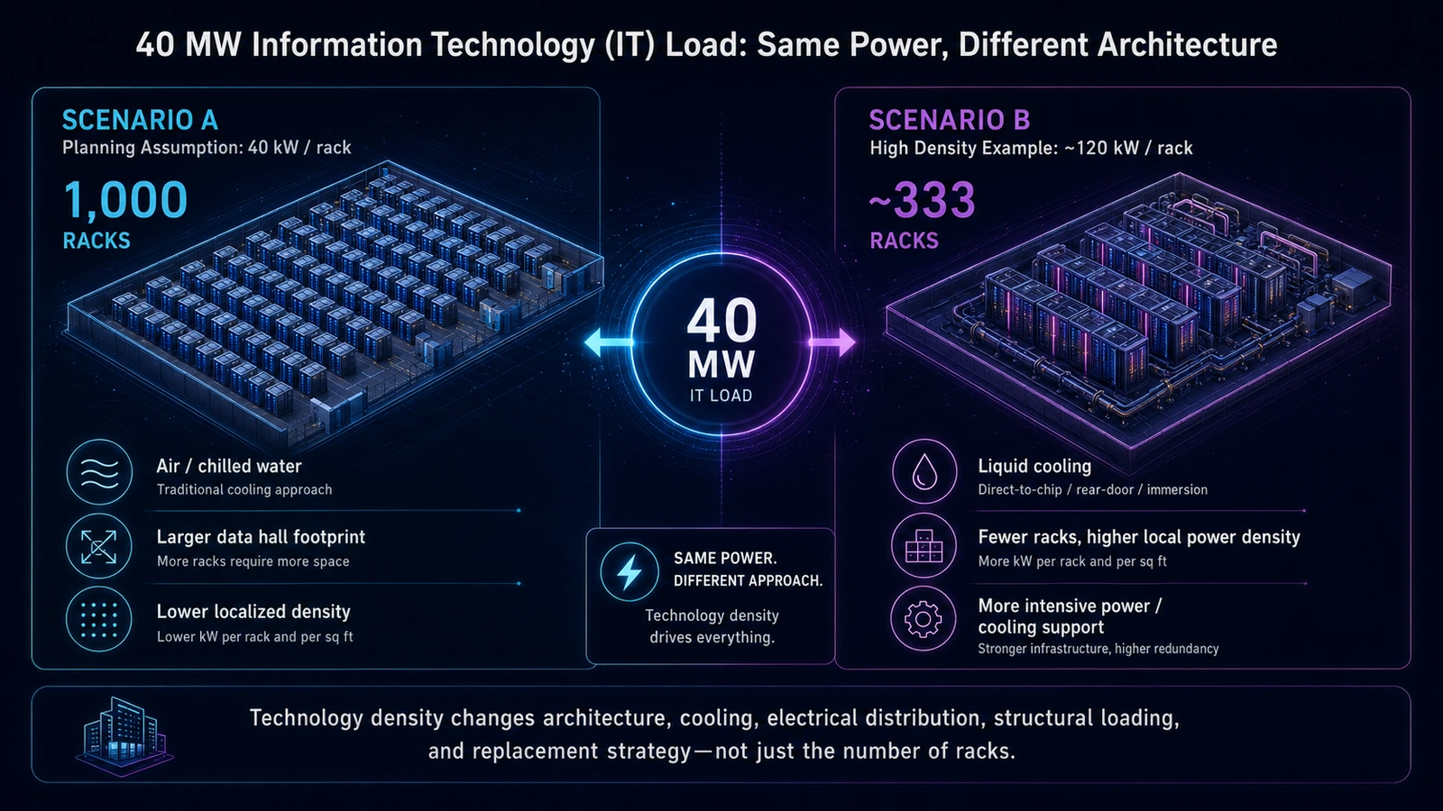
Rack-scale Artificial Intelligence infrastructure evolves faster than traditional building programs. “Rack density = 40 kilowatts per rack” is insufficient. Record initial average rack density, initial maximum rack density, future maximum design density, percentage liquid cooled, electrical distribution limit, cooling architecture limit, structural and loading basis, and service and replacement basis. Current high-density rack-scale systems can exceed 100 kilowatts per rack. Approximately 120 kilowatts per rack is the technology reference example used below: not a universal design requirement and not a code threshold. Confirm selected hardware, rack configuration, power, cooling, weights, clearances, and connections with manufacturers and responsible engineers.
Worked Example: The Same 40 Megawatts Can Produce Very Different Buildings
SCENARIO A — DCFR PLANNING ASSUMPTION Information Technology load: 40 megawatts. Rack density: 40 kilowatts per rack. 40,000 kilowatts ÷ 40 kilowatts per rack = approximately 1,000 racks. This planning-grade scenario implies more racks, a larger white-space footprint, lower localized density, potentially viable conventional air or chilled-water strategies subject to engineering, and a different handling and distribution pattern. SCENARIO B — CURRENT HIGH-DENSITY TECHNOLOGY REFERENCE EXAMPLE Information Technology load: 40 megawatts. Rack density: approximately 120 kilowatts per rack. 40,000 kilowatts ÷ 120 kilowatts per rack = approximately 333 racks. This example implies fewer racks, higher localized power, liquid-cooling infrastructure, CDUs, additional piping and leak detection, greater electrical-distribution intensity, and different structural, maintenance, and replacement demands. Manufacturer and engineering confirmation is required. SAME MEGAWATTS. DIFFERENT TECHNOLOGY. DIFFERENT ARCHITECTURE.
A RACK-COUNT CALCULATION IS NOT A DESIGN; IT IS A TRIGGER FOR COORDINATED ARCHITECTURAL AND ENGINEERING DECISIONS.
The Site Adaptation Process
Pass every reference package through six filters. At each layer classify the result as CONFIRMS REFERENCE, ADAPTS WITHIN APPROVED RANGE, or REQUIRES DEVIATION. Evidence—not familiarity with the prior project—determines the result.
- 1
Layer 1 — Site + utility
Parcel, easements, access, topography, utility, fiber, water, and wastewater.
- 2
Layer 2 — Code + authority
Zoning, adopted building and fire codes, energy, accessibility, amendments, and permitting. Model-code appendices do not automatically apply; confirm local adoption.
- 3
Layer 3 — Hazard + climate
Flood, wind, seismic, hail, snow, wildfire, rainfall, temperature, humidity, and corrosion.
- 4
Layer 4 — Infrastructure
Utility, electrical topology, generators, batteries, cooling, water, heat rejection, and controls.
- 5
Layer 5 — Architecture
Technical rooms, envelope, roof, openings, fire barriers, loading, security, and replacement.
- 6
Layer 6 — Delivery
Local trades, prefabrication, procurement, transportation, crane access, sequencing, and commissioning.
The Deviation Register
A deviation record must identify the reference requirement, proposed change, trigger, affected disciplines, and capacity, reliability, life-safety or code, insurance, utility, cooling, maintainability, cost, schedule, procurement, commissioning, and operations impacts. It also names the decision owner and disposition: site-only, controlled variant, or reference-design update. No blank impact cell means “no impact”; it means unresolved until evidence closes it.
Compact Deviation Record Example
| Reference Requirement | Proposed Change | Trigger | Impacts | Decision / Disposition |
|---|---|---|---|---|
| Liquid-ready data hall module | Vendor-specific CDU room enlargement | Selected equipment service and replacement envelope | Architecture, structure, cooling, cost, schedule, commissioning | Owner approval pending / controlled variant |
The example records workflow only. Dimensions and performance must come from selected-vendor data and responsible engineering.
Version the Reference Design Like a Product
Do not maintain one folder called FINAL STANDARD. Use controlled releases: Reference Design 2026.01 — Initial release; Reference Design 2026.02 — Battery strategy update; Reference Design 2026.03 — Liquid-cooling interface revision. These identifiers are owner-standard examples, not external requirements. Every project records its reference-design version, Basis of Design version, approved deviations, site overlays, and unresolved departures. Uncontrolled drift lets drawings, specifications, procurement packages, commissioning scripts, and operations procedures describe different facilities while carrying the same “standard” label.
A Detail Is Not a Standard Because It Has Been Drawn Twice
PROPOSED ↓ DESIGNED ↓ COORDINATED ↓ PROCURED ↓ BUILT ↓ TESTED ↓ COMMISSIONED ↓ OPERATED ↓ REPEATABLE A detail becomes mature only after the lifecycle tests it. A roof detail that repeatedly leaks is not mature. A technical-room layout that blocks equipment replacement is not mature. A liquid-cooling detail that repeatedly creates maintenance problems is not mature. Record maturity by detail and system rather than awarding an entire drawing set one vague status.
REPETITION IS NOT VALIDATION.
Field Problems Must Feed the Reference Design
At closeout ask what produced repeated Requests for Information, submittal exceptions, redesign, authority objections, field rework, commissioning failures, difficult maintenance or replacement, unexpected shutdown, late vendor information, and performance better than the current standard. Then identify the governing artifact that changes: Owner's Project Requirements, Basis of Design, reference drawing, standard detail, master specification, consultant scope, review checklist, vendor-information deadline, or commissioning requirement.
A LESSONS-LEARNED PRESENTATION THAT NEVER CHANGES A GOVERNING DOCUMENT IS NOT MEANINGFUL STANDARDIZATION.
The Architect's 15-Point Reference-Design Review
Use this gate before a site-specific package advances. Each item needs an owner, evidence, status, and date—not a generic check mark.
- 1
1. Target Information Technology capacity
Approved initial, phase, and ultimate basis.
- 2
2. Rack-density envelope
Initial average, initial maximum, and future maximum.
- 3
3. Artificial Intelligence / liquid cooling
Technology percentage and interface requirements.
- 4
4. Utility configuration
Capacity, voltage, routes, schedule, and dependencies.
- 5
5. Cooling architecture
Technology family, limits, water, and heat rejection.
- 6
6. Battery strategy
Chemistry, arrangement, replacement, and project fire basis.
- 7
7. Adopted building code
Edition, amendments, and interpretations confirmed.
- 8
8. Adopted fire code
Edition, amendments, and fire-department process confirmed.
- 9
9. Energy requirements
Adopted and contractual criteria reconciled.
- 10
10. Natural hazards
Current site evidence and mitigations documented.
- 11
11. Envelope / climate response
Site-appropriate assemblies and interfaces.
- 12
12. Fire and life-safety assumptions
Occupancy, construction, compartments, egress, detection, and suppression.
- 13
13. Equipment maintenance clearances
Vendor and engineer requirements coordinated.
- 14
14. Full equipment replacement route
Continuous path demonstrated in plan, section, and sequence.
- 15
15. Owner / insurer / Authority Having Jurisdiction deviations
Named approval and downstream impacts recorded.
Common Reference-Design Failures
Treat these as separate control failures with separate corrective actions.
- 1
FAILURE 1
Copying drawings instead of controlling requirements.
- 2
FAILURE 2
Using one rack-density assumption forever.
- 3
FAILURE 3
Embedding one code edition permanently into the prototype.
- 4
FAILURE 4
Using “typical” clearances with no identified source.
- 5
FAILURE 5
Making site exceptions informally.
- 6
FAILURE 6
Ignoring equipment replacement.
- 7
FAILURE 7
Keeping lessons learned only in presentations.
- 8
FAILURE 8
Updating the prototype without version control.
STANDARDIZE THE INTENT, INTERFACES, AND PROVEN SOLUTIONS. REVALIDATE THE SITE, CODE, UTILITY, HAZARDS, EQUIPMENT, AND DELIVERY CONDITIONS EVERY TIME.
Conditions of Approval Must Flow Into the Basis of Design
Entitlement plans, proffers, development conditions, staff requirements, utility agreements, permit conditions, and representations in the public record can create durable project obligations. Capture each item at its source and translate it into controlled technical and operational requirements. The trace should remain visible through the Owner's Project Requirements, Basis of Design, reference-design interface, site adaptation, discipline documents, procurement, permit review, construction verification, and facilities procedures. A condition is not closed because it appears on one drawing.
Condition-to-Basis-of-Design Traceability Matrix
| Condition or commitment | Source and applicability | Responsible owner | BOD or standard location | Design and procurement record | Verification and operations |
|---|---|---|---|---|---|
| Approved buffer and setback | Entitlement plan, proffer or resolution; affected parcel and phase | Land-development lead | Civil, landscape and architectural criteria | Site plan, survey controls and landscape package | As-built survey, inspection and maintenance plan |
| Generator testing and property-line sound | Ordinance, hearing statement or approval condition | Acoustics and operations leads | Acoustic performance and controls basis | Equipment schedule, submittals, enclosure and controls | Field test, testing procedure and compliance log |
| Approved access and traffic routing | Traffic condition, site plan or agency agreement | Civil and construction leads | Roadway, fire-access and logistics criteria | Civil plans, contracts and logistics plan | Agency acceptance, delivery controls and operational routing |
| Water-use or discharge obligation | Utility agreement, permit or public commitment | Utilities lead | Water balance, metering and system controls | Equipment selection, piping, meters and reporting setup | Commissioning evidence and continuing compliance report |
| Landscape, lighting and visual mitigation | Entitlement condition or approved plan | Planning and architecture leads | Exterior, landscape and lighting criteria | Plans, fixture data, procurement and installation record | Closeout inspection and facilities maintenance |
Land-use counsel, the applicable authority, and the owner should confirm the legal source, interpretation, applicability, and closure evidence for each obligation.
Current Technical Basis — August 2026
International Code Council
2024 International Building CodeModel-code reference basis; verify locally adopted edition and amendments.
International Code Council
2024 International Fire CodeModel-code reference basis; verify locally adopted edition, amendments, and appendices.
American Society of Heating, Refrigerating and Air-Conditioning Engineers (ASHRAE)
ANSI/ASHRAE Standard 90.4-2025 — Energy Standard for Data CentersUse where applicable; confirm adopted or contractual project criteria.
National Fire Protection Association (NFPA)
Codes and StandardsConfirm the current adopted National Electrical Code and project-applicable data-center and stationary energy-storage standards.
NVIDIA
Data Center Product DocumentationConfirm current rack-scale hardware power, cooling, weight, service, and installation requirements for selected equipment.
Schneider Electric
Data Center Reference DesignsUse current high-density and liquid-cooling materials as technology references, not universal project requirements.
Technical basis reviewed August 2026. Cooling technology, equipment capability, vendor qualification, and industry guidance continue to evolve; project decisions should use the latest applicable manufacturer data and professional engineering analysis.
Capacity-delivery review checklist
What to verify before the next release gate.
- Confirm the reference-design and Basis of Design versions and all approved deviations.
- Trace every technical value to code, manufacturer, engineering, owner, planning, or project-confirmation status.
- Demonstrate site adaptation, equipment maintenance, complete replacement, and commissioning closure.
- Trace entitlement and permit conditions through the OPR, BOD, design, verification, and operational owner.
What DCFR would flag
Delivery risks that should be visible early.
DCFR would flag a project when the reference-design version is unknown; rack density is outdated or undefined; adopted code is unverified; dimensions lack a basis; site hazards remain unresolved; replacement cannot be demonstrated; owner or insurer criteria are unconfirmed; deviations lack named approval; or technology exceeds the approved performance envelope.
Professional confirmation required
Items requiring project-specific validation.
Code adoption, local amendments, Authority Having Jurisdiction interpretation, utility service, hazards, insurer criteria, structural and engineering values, manufacturer clearances, rack technology, cooling architecture, battery strategy, energy requirements, commissioning acceptance, and every planning allowance require confirmation for the actual project.
Final takeaway
A DATA CENTER REFERENCE DESIGN SHOULD NOT FREEZE A BUILDING. IT SHOULD FREEZE THE CRITICAL PERFORMANCE INTENT, DEFINE THE RANGE OF ACCEPTABLE CHANGE, AND PROVIDE A CONTROLLED METHOD FOR ADAPTING TO THE NEXT SITE AND THE NEXT GENERATION OF TECHNOLOGY.
Surface site, code, utility, and delivery risk before it becomes expensive.
DCFR converts early assumptions into planning-grade flags, confirmation registers, and decision-ready feasibility outputs.