
DCFR Insight 107 / Fire + Constructability
Firestopping as a Manufactured System: From Field Variability to Repeatable Performance
A deep-dive on treating penetrations, sleeves, cable pathways, tested assemblies, inspection, and change control as one repeatable fire-and-smoke-containment system.
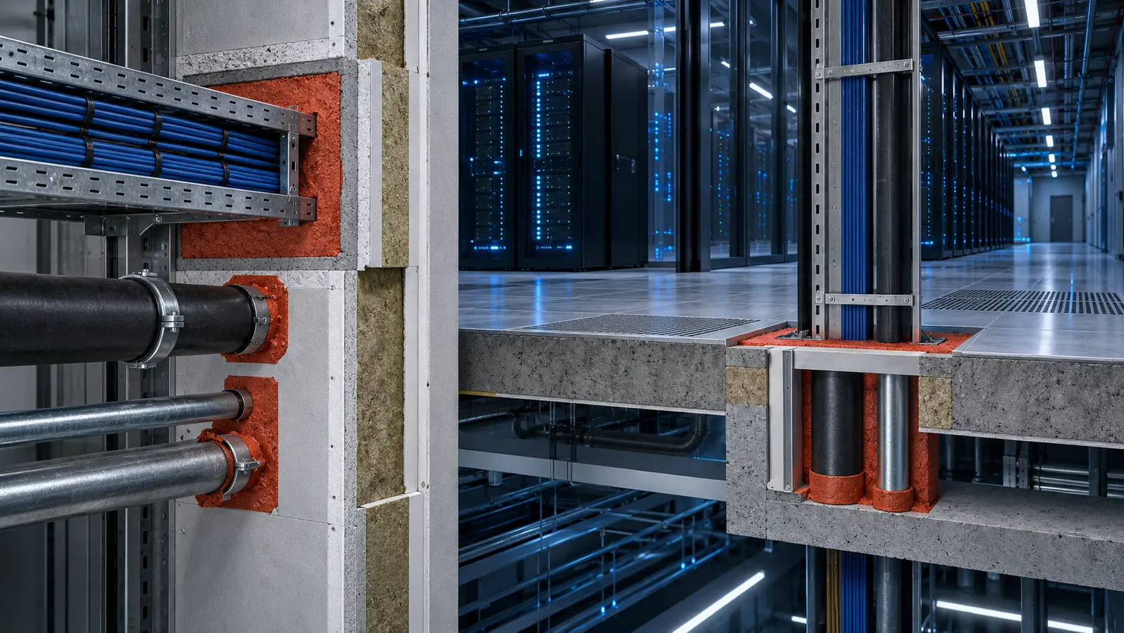
The Penetration Is an Interface, Not a Sealant Detail
A rated wall or floor delivers a required fire-resistance and often smoke-containment function only while its openings are controlled. Data centers contain dense, evolving penetrations for power, controls, fiber, cooling, drainage, refrigerant, conduit, cable trays, and future capacity. The penetration is therefore a multi-discipline interface with a life after construction.
Field variability becomes dangerous when the design treats firestopping as a late trade scope. Congested openings, changed cable fills, unplanned sleeves, inaccessible backsides, incompatible materials, and undocumented repairs can break the evidence chain between a tested system and the installed condition.
The goal is not to maximize a single product. It is to engineer a limited family of applicable assemblies that can be coordinated, installed, inspected, altered, and restored without improvisation.
Understand What the Test Actually Represents
A listed or tested assembly is evidence for a defined condition: supporting construction, opening size, penetrant type and size, annular space, packing, fill, orientation, materials, and installation method. It is not permission to apply a familiar product to any opening.
Project teams must compare the actual condition to the tested system rather than rely on a generic product data sheet. Mixed penetrations, uncommon substrates, oversized openings, unusual cable trays, movement, pressure, moisture, and service temperature can change applicability.
Where the installed condition cannot conform to a tested system, the project needs a defensible engineered judgment or alternate approved path from qualified parties, subject to code and AHJ requirements.
RATED OPENING ANATOMY
Firestopping is a tested system, not a tube of sealant.
Every part of the installed condition must match the evidence.
BARRIER
Rated wall or floor construction
PENETRANT
Cable, tray, pipe, conduit, mixed service
SYSTEM
Annular space, backing, fill, installation limits
STUDY NOTE — EVIDENCE + FAILURE MODE
Study point: a listed firestop system applies only to its defined construction, penetrant, annular space, backing, fill material, orientation, and installation method; a generic product sheet is not evidence.
Standardize the Penetration Family Before Coordination Closes
Repeatability begins with a penetration taxonomy: wall or floor type; fire-resistance and smoke requirements; service type; diameter or tray range; future-capacity need; movement; environmental exposure; accessibility; and anticipated modification frequency.
The team can then define preplanned opening zones, sleeves, cast-in devices, modular cable transits, curb and roof-penetration details, and inspection access. This reduces the number of unique conditions that must be resolved under field pressure.
Standardization must still respect the actual building and services. A module that makes routing impossible will be bypassed; a bypassed firestop plan becomes an uncontrolled firestop plan.
Manufacture Quality Through Sequence and Inspection
For recurring conditions, the most reliable model resembles manufacturing: approved assembly selection, issued detail, controlled materials, installer competency, preparation, installation sequence, in-process inspection, record, and closeout.
Inspection should occur when the condition is visible. Once cable trays are filled, ceilings close, or equipment is energized, the team may no longer be able to verify backing, depth, annular space, or material continuity.
The record should connect location, barrier type, required rating, penetrant condition, approved system, installer, inspection, photographs, correction history, and later modification status.
CONDITION MATCHING
Select a tested system for the actual penetration—not the familiar product.
Changes in substrate, size, fill, or service can break applicability.
CLASSIFY
Wall/floor, rating, orientation, services
MATCH
Listed system and permitted limits
ESCALATE
Engineered judgment or approved alternative
STUDY NOTE — EVIDENCE + FAILURE MODE
Evidence required: establish the penetration family before coordination closes, then record the system ID, location, installer, installation photo, inspection result, and any engineered judgment.
Design for Controlled Future Change
Data centers evolve. Cable additions, controls modifications, equipment replacements, and fit-out changes can quickly invalidate an otherwise compliant condition. A firestop strategy that only works at substantial completion is not an operational strategy.
Use purpose-built pathways and modular systems where the change frequency and criticality justify them. Define who may modify each barrier, what review is required, how temporary openings are protected, who reinstalls the system, and how the record is updated.
Change control is essential because a series of individually minor penetrations can erode a compartment boundary without appearing in the original closeout package.
Owner-Side Decision Matrix
| Decision | What must be defined | Evidence before release |
|---|---|---|
| Performance basis | Required operating outcome, capacity range, failure and maintenance states | Requirement trace, calculation, test method, acceptance threshold |
| Physical interface | Geometry, tolerance, access, ownership, safety and sequence | Coordinated model/detail, manufacturer data, constructability review |
| Variant boundary | What may vary and what must remain controlled | Applicability matrix, deviation approval, configuration record |
| Lifecycle outcome | Inspection, maintenance, replacement, recovery and future phase implications | Operations review, replacement-path test, commissioning and handover plan |
Integrate Firestopping With Commissioning and Operations
Commissioning focuses on active systems, but passive protection controls the environment in which active systems operate. Impairment procedures, inspection programs, access plans, and modifications must connect to the facility’s operational governance.
At handover, operations needs a barrier map, approved-system library, inspection and repair protocol, material compatibility information, change authorization route, and escalation path for unlisted conditions.
The owner should monitor recurrent failures by location, system, trade interface, and project phase. That converts passive-protection defects into reference-design learning.
QUALITY CONTROL LOOP
Make every rated opening inspectable and traceable.
Future capacity work is a controlled change.
01 PREPLAN
Coordinate sleeves and pathway family
02 INSPECT
Photo, ID, installer, system, location
03 CONTROL
Review later cables, pipes, repairs
STUDY NOTE — EVIDENCE + FAILURE MODE
Failure to avoid: allowing future cable or pipe work to modify a rated opening without review. Every later intervention must re-establish the tested or approved condition.
Early screening checklist
What to verify before advancing this site.
- Rated barriers and penetration families are mapped.
- Installed conditions are checked against tested/approved assemblies.
- Preplanned openings and future-capacity pathways are coordinated.
- Inspection happens before concealment.
- Modification authority and repair process are defined.
- Handover includes barrier records and operating controls.
What DCFR would flag
Risks surfaced at the screening stage.
DCFR should flag whether the reference design can support a coherent compartmentation and penetration strategy; final fire-resistance, smoke-control, listing, and code determinations require project evidence.
Professional confirmation required
Items requiring licensed validation.
Planning-grade guidance only. Final design requires adopted-code, AHJ, fire-protection engineer, architect, manufacturer, installer, inspector, insurer, and operations confirmation.
Final takeaway
Firestopping becomes repeatable when the project controls the opening, the assembly, the installation, the inspection, and the future change—not merely the product name.
Screen up to 20 candidate sites before selecting one for the full DCFR report.
Each DCFR Report Package includes a preliminary 20-site comparison PDF / export package plus one selected planning-grade feasibility report.