
DCFR Insight 47 / Extreme-Density Infrastructure
Extreme-Density Data Center Planning: 100 kW to 1 MW per Rack
Extreme rack density changes much more than cooling. It reshapes electrical distribution, hydraulics, structure, fire strategy, service access, controls, commissioning, and the size of every credible failure domain.
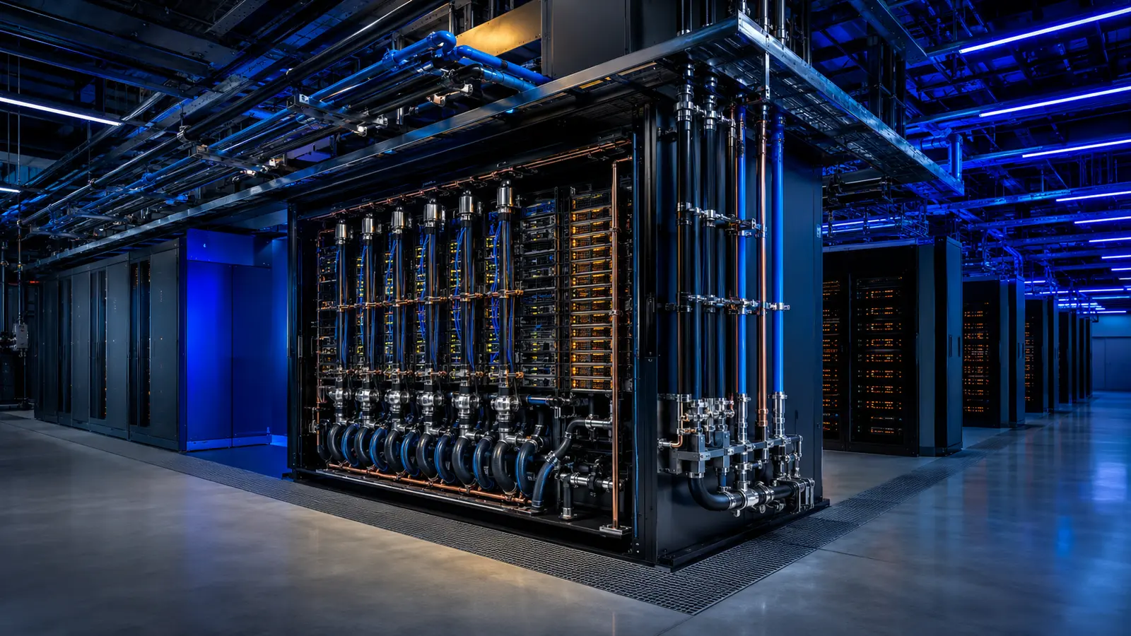
Replace average density with a rack-by-rack scenario model
A room average hides the concentration that drives conductor size, busway topology, coolant flow, floor loading, service clearances, and failure impact. Build a rack schedule for initial, committed, and ultimate technology cohorts. For each rack or neighborhood, state maximum and expected power, heat split to liquid and air, voltage, connector architecture, coolant supply and return conditions, flow, pressure, weight, dimensions, cabling, and replacement method. Include diversity only where workload evidence supports it, and retain a non-diversified case for protective and life-safety decisions.
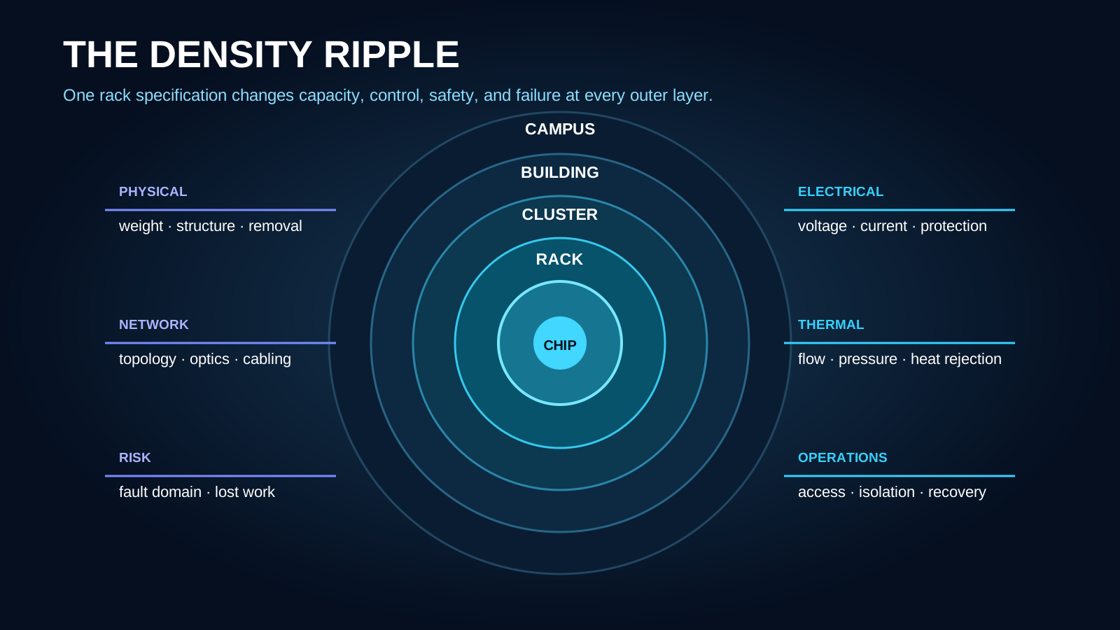
Follow the density ripple from silicon to site
Higher chip power raises rack heat, which increases coolant flow and electrical current, which enlarges distribution, pumping, heat rejection, structural reactions, and fault consequences. At extreme density, a small group of racks can equal a traditional data hall. Define the chain from chip, server and rack through row, cluster, cooling distribution unit, power train, building, and campus. At every boundary document capacity, controllable range, stored energy, isolation, monitoring, access, and recovery. This creates a traceable basis for both engineering and commercial commitments.
Select rack power architecture as a system decision
Compare alternating-current and higher-voltage direct-current approaches against current equipment availability, conversion efficiency, fault behavior, protection, touch safety, grounding, standards, maintainability, connector maturity, and operator competence. Coordinate utility voltage, transformers, UPS or ride-through, rectification, busway, rack power shelves, and cable routing. Model simultaneous ramp and restart behavior rather than multiplying nameplate ratings. Preserve a clear isolation boundary so one extreme-density rack does not make a whole cluster unsafe to service.
Rack-Density Scenario Inputs
| Input | Baseline case | Stress case | Evidence required |
|---|---|---|---|
| Rack power | Expected sustained workload | Maximum credible synchronized demand | Current platform and workload data |
| Heat split | Normal liquid-to-air ratio | Loss or degradation of liquid capture | Manufacturer thermal envelope |
| Coolant | Normal temperatures, flow and pressure | Turndown, ramp and distant-branch case | Hydraulic model and equipment curves |
| Electrical | Normal power factor and conversion | Step, restart, harmonics and fault | Time-based power model |
| Physical | Installed rack and service envelope | Replacement and emergency intervention | Verified equipment and logistics data |
The title describes an emerging planning range, not a claim that every project should target a 1 MW rack. Use equipment-specific values.
Engineer coolant delivery for control, cleanliness, and containment
Determine technology-cooling-system heat load, approach temperatures, flow, differential pressure, permissible ramp, water quality, materials, filtration, degassing, expansion, make-up, drain, leak detection, and secondary containment. Size pipes and cooling distribution units for credible technology cohorts and turndown. Verify valve authority and control stability across near and distant branches. Separate clean technology loops from facility loops through an intentional interface. Provide flushing connections, sampling, temporary filtration, spill response, and replaceable flexible connections without compromising adjacent live racks.
Recalculate structure, fire strategy, and human access
Confirm rack static and rolling loads, concentrated floor reactions, anchorage, seismic restraint, raised-floor limits where used, overhead distribution support, ceiling congestion, and equipment movement. Revisit fire detection, suppression, drainage, coolant properties, energized-work boundaries, egress, aisle width, lifting, and emergency response. Dense liquid-cooled racks can be taller, deeper, heavier, and more connected than conventional cabinets. A layout that fits in plan may still be impossible to install, service, or remove safely.
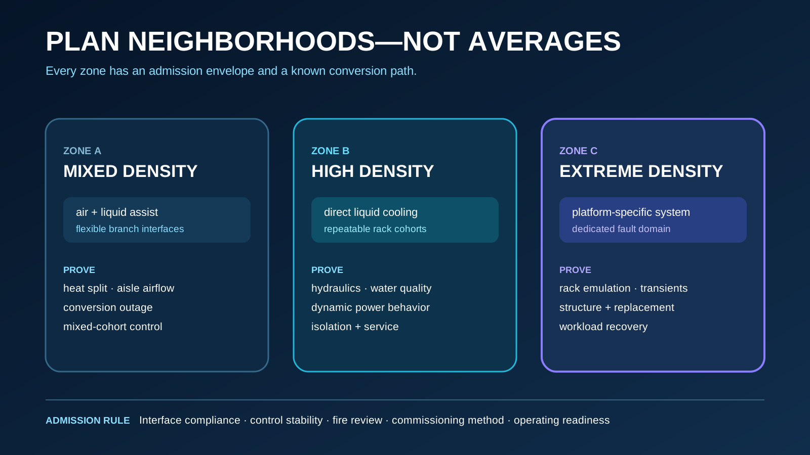
Zone the building for heterogeneous generations
Few campuses convert to one extreme density at once. Create density neighborhoods with defined electrical, cooling, structural, network, and control envelopes. Locate mixed air-cooled, liquid-assisted, and direct-liquid-cooled cohorts without allowing one to destabilize another. Protect headers, bus routes, floor zones, and service corridors for conversion. Establish admission criteria for a new rack type: interface compliance, transient behavior, heat split, water chemistry, weight, fire review, controls integration, and demonstrated commissioning method.
Design fault domains around lost work and safe intervention
A cooling distribution unit, bus section, switchboard, or header serving extreme-density racks may contain enormous computational value. Select the domain by workload checkpointing, restart time, maintenance frequency, spare strategy, isolation speed, leak consequence, and acceptable lost work—not by inherited data-hall conventions. Test partial-flow, pump loss, control failure, fast isolation, utility disturbance, UPS transition, and restart sequences. Provide thermal ride-through consistent with the actual silicon response and control latency.
Commission with emulators before risking production hardware
Use hydraulic cleaning and verification, instrument calibration, protection testing, control tuning, and heat or rack emulation to prove the infrastructure across minimum, normal, peak, transient, and failure modes. Confirm each rack interface before connection. Then stage platform commissioning and representative workload tests. Record pressure, flow, temperature, power quality, harmonics, alarms, valve states, leak response, and recovery on one timeline. Nameplate capacity is not accepted capacity until the system remains controlled under realistic dynamics.
Extreme-Density Readiness Gates
| Gate | Pass condition | Failure if skipped |
|---|---|---|
| Zone admitted | Electrical, thermal, structural, fire and service envelopes approved | The room fits the rack but the facility cannot support it |
| Infrastructure proven | Distribution and cooling operate across dynamic and failure modes | Controls become unstable under real load |
| Interface released | Power, coolant, network and physical connections verified | Damage, contamination or unsafe connection |
| Platform released | Telemetry and platform health remain within limits | Silent throttling or repeated component faults |
| Workload accepted | Representative work completes and recovers predictably | High nameplate capacity with poor productive output |
Retain optionality without building speculative capacity everywhere
Extreme-density readiness should be specific. Reserve backbone corridors, connection points, structural zones, electrical voltage options, heat-rejection expansion, and controls capability, while installing branch capacity in step with committed cohorts. Define the cost and outage required to convert each zone. This produces an investable roadmap between today's platform and a plausible upper bound, avoiding both a stranded overbuild and a campus that cannot accept commercially important hardware.
Early screening checklist
What to verify before advancing this site.
- Initial, committed, and ultimate density are mapped rack by rack
- Each cohort states power, heat split, coolant, weight, dimensions, and connections
- Time-based electrical models include ramps, steps, restart, and harmonics
- Technology and facility cooling loops have a controlled, owned interface
- Hydraulic design proves turndown, distant branches, cleanliness, and leak response
- Structure, anchorage, egress, fire strategy, lifting, and removal are verified
- Density zones isolate different technology generations and operating envelopes
- Fault-domain size reflects lost work, ride-through, maintenance, and recovery
- Infrastructure is proven with emulation before production hardware is exposed
- Every future-ready zone has a defined conversion scope, cost, and outage
What DCFR would flag
Risks surfaced at the screening stage.
DCFR would flag an extreme-density proposal based on average room density or rack nameplate alone, without time-based power behavior, liquid-loop ownership, hydraulic proof, structural and service verification, fault-domain analysis, and representative workload acceptance.
Professional confirmation required
Items requiring licensed validation.
Confirm rack power, cooling, dimensions, weight, electrical characteristics, coolant chemistry, controls, fire strategy, service access, commissioning, and future technology assumptions with current equipment manufacturers, the owner, utility, licensed professionals, contractors, insurers, and authorities.
Final takeaway
Extreme density is a campus-level engineering condition: every rack must be traced through power, coolant, structure, controls, failure, service, and useful workload output.
Screen up to 20 candidate sites before selecting one for the full DCFR report.
Each DCFR Report Package includes a preliminary 20-site comparison PDF / export package plus one selected planning-grade feasibility report.