
DCFR Insight 106 / Lifecycle Architecture + Operations
Designing for Replaceability: Architectural Systems for Rapid Equipment Change-Out
How to design the permanent routes, clearances, removable assemblies, and operational protections that turn equipment replacement from an emergency redesign into a planned lifecycle task.
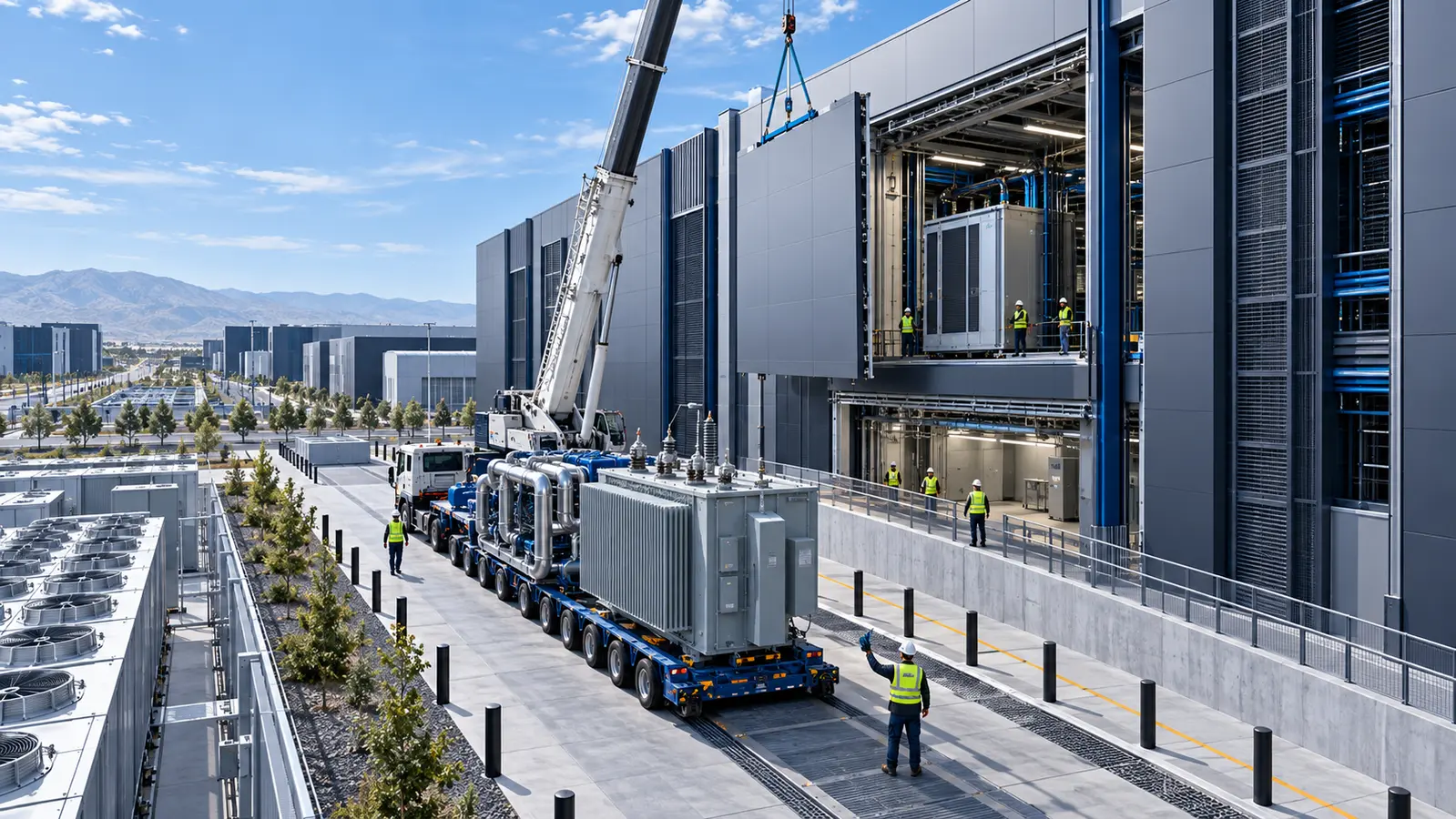
Replacement Is a Design Load
Major electrical and mechanical equipment has a replacement life that is usually shorter than the building and may be shorter than the campus program. Architecture therefore has to carry a lifecycle load: the physical ability to remove, move, isolate, protect, and reinstall critical assets without dismantling the facility around them.
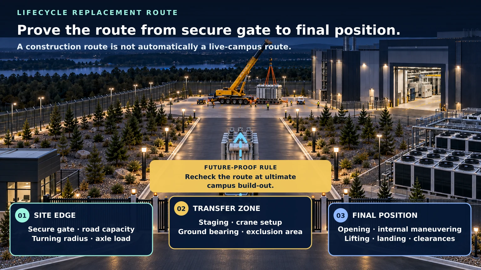
The route begins at the property boundary, not at the equipment-room door. A replacement study must include secure gate geometry, road capacity, turning, staging, crane setup, structural path, delivery opening, vertical movement, internal maneuvering, temporary weather protection, and return-to-service sequence.
A route that works only during greenfield construction is not a replacement route. Once the site is live, security, parking, landscaping, later phases, pipework, cabling, and temporary operations can consume the apparent clearance.
Start With the Largest and Least Forgiving Item
Build the design envelope from the heaviest, longest, widest, tallest, and most sensitive credible replacement item—not the easiest item to move. That may be a transformer, generator, UPS module, battery string, CRAH, chiller component, CDU, switchgear lineup, or large fan array.
Document shipped dimensions, weights, center of gravity, lifting points, allowable tilt, preservation conditions, disconnect limits, rigging requirements, door and hatch clearances, temporary support needs, and manufacturer restrictions.
The objective is not a theoretical route. It is a verified movement scenario with a clear sequence, responsible party, needed temporary works, operating constraints, and unacceptable conditions.
Create a Hierarchy of Access
A reliable building separates routine technician access, component-level maintenance, major component replacement, and catastrophic recovery. Each has different clearance, security, structural, and operational requirements.
Routine access needs safe walking, lighting, working space, tool clearance, and no-conflict circulation. Major replacement may need removable façade panels, equipment doors, roof hatches, overhead lifting, protected corridors, slab capacity, and temporary exclusion zones.
Do not allow a one-time replacement event to drive needless excess space everywhere. Instead, create purposeful transfer points and defined replaceable zones where the lifecycle case justifies them.
Coordinate Structure, Envelope, and Fire Strategy
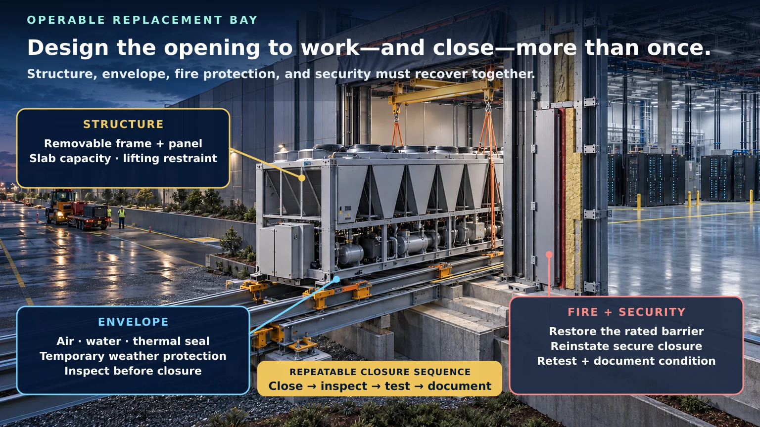
The replacement path is an architectural assembly, not only a logistics plan. Slabs and suspended elements may need localized capacity. Exterior openings need weather, air, water, thermal, and security continuity after repeated removal. Fire barriers must retain their rating after equipment movement and reconnection.
A removable bay should be treated as a system: demountable framing, panel or door, seals, fasteners, lifting method, access, weather limitations, inspection, restoration test, and security condition.
If the route penetrates a rated boundary, define the tested or engineered restoration condition before the first installation. ‘Close it up afterward’ is not a fire strategy.
Plan Isolation and Operating Continuity
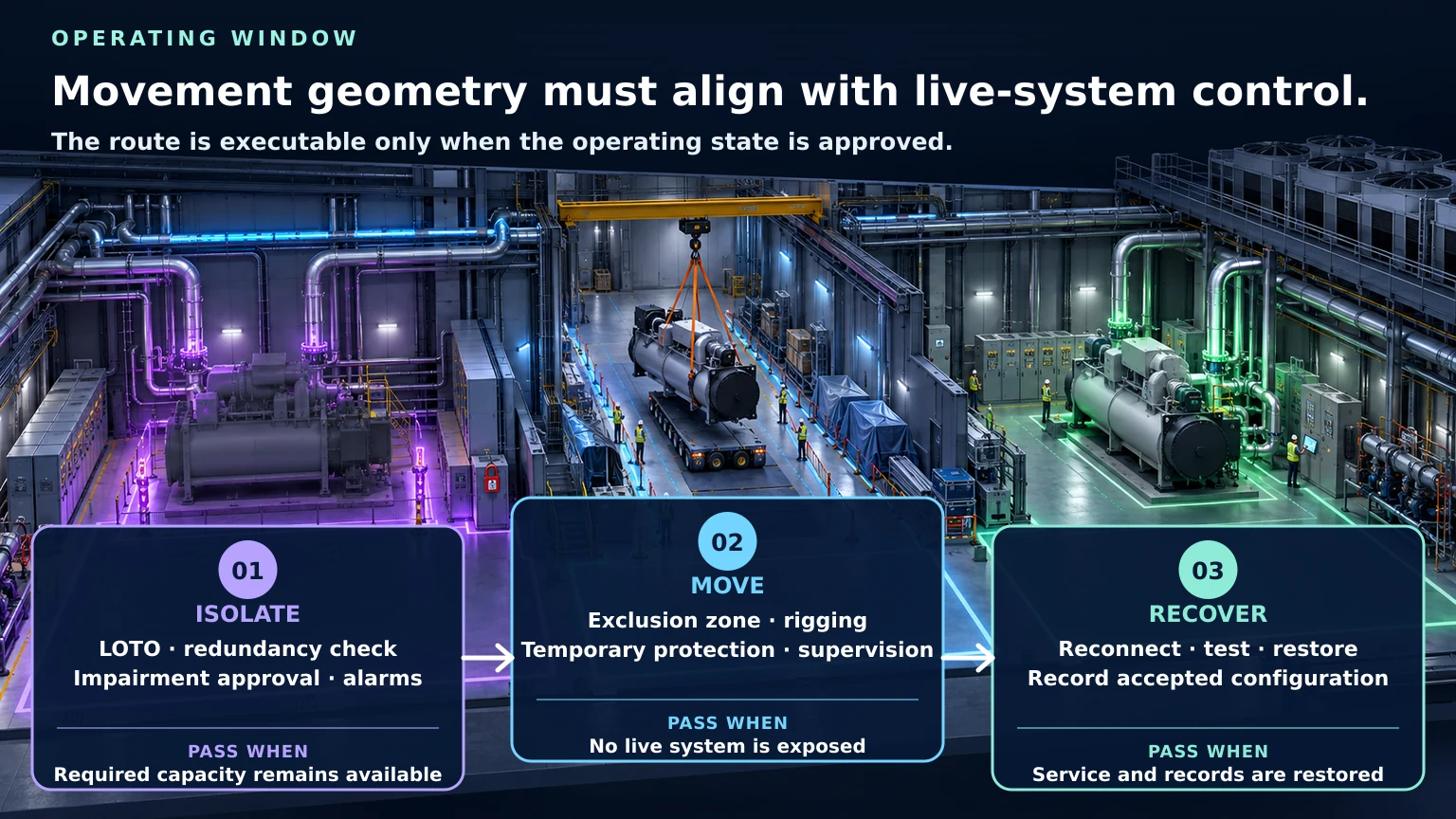
Equipment movement in a mission-critical facility often occurs while adjacent capacity remains live. The plan must distinguish mechanical movement from electrical isolation, control-system isolation, fire-protection impairment, security controls, and operational risk.
For each event, define what remains energized, what is isolated, what redundancy is consumed, what alarms are inhibited, what temporary protection is added, who approves the window, and what condition stops the work.
The replacement-path drawing should link to the operating method. Geometry without switching, lockout/tagout, impairment control, and recovery sequencing is not an executable lifecycle plan.
Owner-Side Decision Matrix
| Decision | What must be defined | Evidence before release |
|---|---|---|
| Performance basis | Required operating outcome, capacity range, failure and maintenance states | Requirement trace, calculation, test method, acceptance threshold |
| Physical interface | Geometry, tolerance, access, ownership, safety and sequence | Coordinated model/detail, manufacturer data, constructability review |
| Variant boundary | What may vary and what must remain controlled | Applicability matrix, deviation approval, configuration record |
| Lifecycle outcome | Inspection, maintenance, replacement, recovery and future phase implications | Operations review, replacement-path test, commissioning and handover plan |
Prove the Route Before the Campus Is Full
Use digital clearance studies, turn-path analysis, rigging review, and physical mockups where risk is high. Validate at ultimate build-out, not just Phase 1, because later buildings, gates, utility corridors, and landscaping may block the original route.
Keep an authoritative replacement-route register with asset, path, permitted obstructions, temporary-work needs, structural limits, last validation date, responsible owner, and triggers for revalidation.
Every project change that touches roads, overhead distribution, fencing, openings, room layouts, or adjacent development should be screened against this register.
Early screening checklist
What to verify before advancing this site.
- Largest credible equipment movement is documented.
- Secure site-to-equipment route is continuous.
- Doors, hatches, slabs, openings, and rigging points are verified.
- Fire, envelope, and security restoration are defined.
- Isolation, impairment, redundancy, and recovery are coordinated.
- Ultimate build-out has been tested for route survival.
What DCFR would flag
Risks surfaced at the screening stage.
DCFR should identify early whether building placement, perimeter security, road geometry, utility yards, future phases, and sensitive-edge buffers preserve the major-equipment replacement path.
Professional confirmation required
Items requiring licensed validation.
Planning-grade guidance only. Final replacement design requires equipment-vendor, logistics, structural, architectural, MEP, fire-protection, security, operations, insurer, and AHJ confirmation.
Final takeaway
A facility is more resilient when the hardest replacement event has been designed, tested, and protected before an outage makes it urgent.
Screen up to 20 candidate sites before selecting one for the full DCFR report.
Each DCFR Report Package includes a preliminary 20-site comparison PDF / export package plus one selected planning-grade feasibility report.