
DCFR Insight 104 / Campus Planning + Capacity Delivery
10 Steps to Plan the Ideal Data Center Masterplan
A practical architect-led sequence for placing the data halls, power, cooling, generators, loading, parking, fire access, stormwater, buffers, utility corridors, and future expansion so the campus works as one operating system—not a collection of rectangles.
1. Define the Real Buildable Envelope
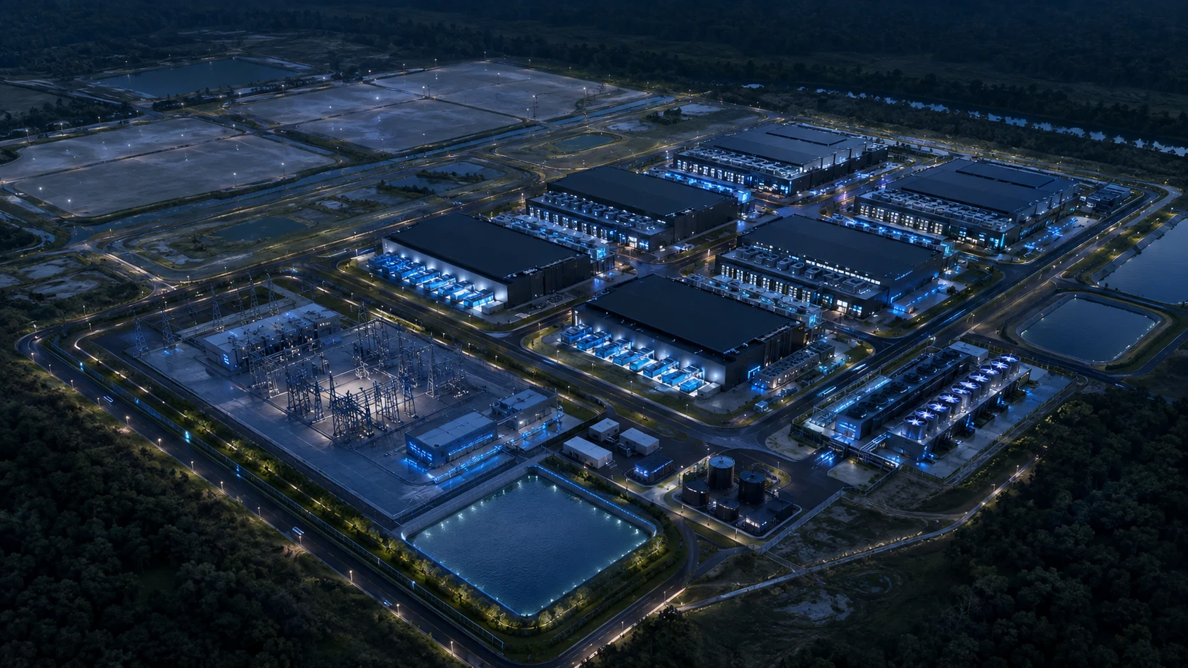
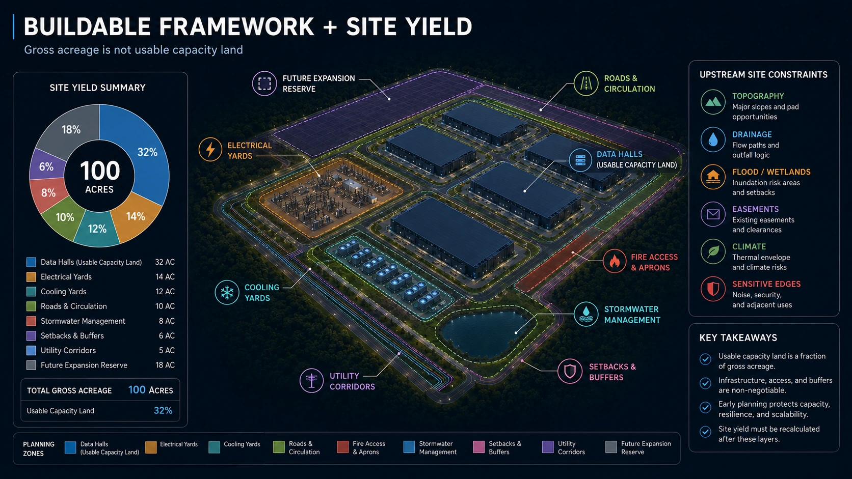
Do not start by drawing the data center building. First determine what land can actually support development after setbacks, easements, flood exposure, wetlands, drainage corridors, topography, utility rights-of-way, access constraints, security setbacks, and sensitive-edge buffers are accounted for.
Gross acreage is not usable data-center acreage. Preserve the largest, most regular portion of the buildable envelope for capacity-producing uses. Irregular corners, drainage areas, and constrained strips may be better suited to stormwater, landscape buffers, or secondary circulation.
The common failure is to design against the parcel boundary and discover later that civil, environmental, or legal constraints remove the land needed for a second data hall or electrical yard.
2. Convert MW Into Physical Building Demand
Translate the target IT load into real building geometry before placing the facility on the site: IT MW → rack density → rack count → data hall modules → building footprint.
For example, a 40 MW IT program at 40 kW per rack is approximately 1,000 racks. Instead of drawing one undefined 40 MW box, organize that requirement into repeatable data-hall modules and the support space needed around them.
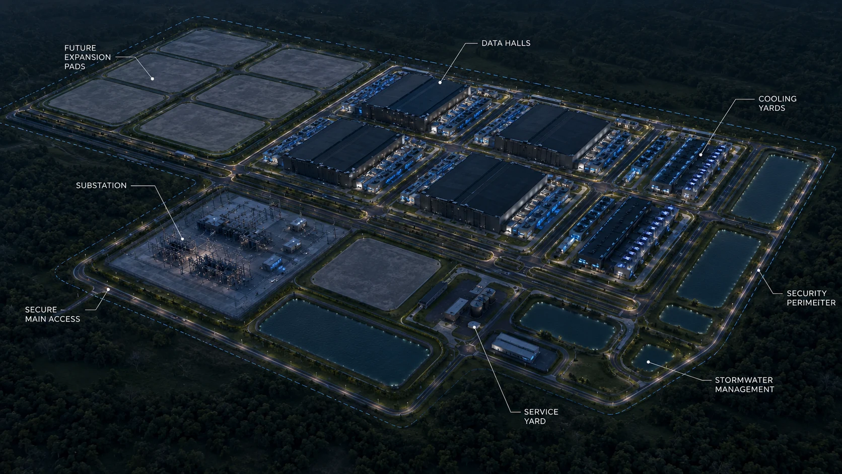
Place the data halls on the best regular development pad, align them efficiently with parcel geometry, and preserve infrastructure space around them. The geometric center of the property is not automatically the best operational location.
 Open full-size plan ↗
3. Establish the Power Spine
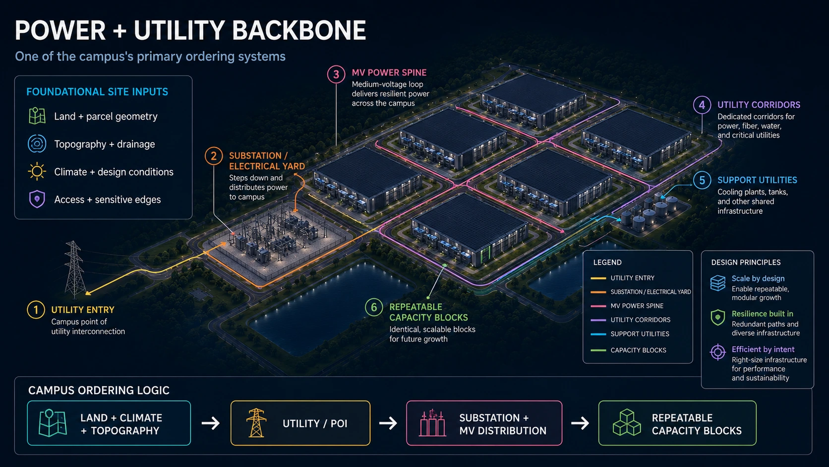
Identify the utility approach, likely point of interconnection, substation, transformer and switchgear yards, protected distribution corridor, generator relationship, and future power expansion before the campus fills up.
The preferred sequence is Utility → Substation → Electrical Yard → Data Center. Keep the route direct while preserving heavy-equipment delivery, maintenance access, security separation, flood protection, and future growth.
Think of electrical infrastructure as a campus backbone, not a leftover service block. A substation that fits today but cannot expand or be serviced later is not a successful masterplan.
4. Put Cooling Where It Can Actually Perform
Cooling and heat-rejection infrastructure needs proximity to the load, clear airflow, maintenance access, replacement paths, acoustic consideration, and—depending on the system—water and treatment infrastructure.
Do not squeeze cooling equipment into enclosed leftover pockets. Locate it adjacent to the data halls it serves, but give it enough open-air exposure for intake, discharge, service, and equipment replacement.
Where residential or other sensitive uses exist, favor the less sensitive edge when technically feasible. For high-density AI facilities, remember that reduced white-space area does not necessarily reduce electrical and thermal-support intensity.
 Open full-size plan ↗
5. Create a Dedicated Heavy-Service Zone
Group compatible industrial functions where possible: generator yards, fuel systems, loading, truck staging, maintenance, equipment replacement, and major mechanical/electrical servicing.
Place this zone along the service-access side rather than the primary visitor frontage. Maintain direct heavy-vehicle access and keep noisy or industrial systems away from sensitive neighboring uses when the site allows it.
Scattering generators, loading, fuel, and maintenance areas around multiple sides of the building may make individual pieces fit, but it usually creates operational conflict and weak long-term serviceability.
6. Separate People From Trucks
Staff and visitor circulation should not routinely compete with tractor-trailers, fuel trucks, cranes, or major-equipment deliveries.
A clear arrival sequence is Public Road → Security Gate → Visitor/Staff Parking → Administration or Main Entry. A separate or clearly segregated service sequence is Service Gate → Truck Route → Loading/Truck Court → Generator, Cooling, Fuel, and Electrical Service Areas.
Parking should be sized from staffing, visitors, contractors, accessibility, and local requirements—not wrapped around the building simply because land is available.
7. Protect Fire Access and Equipment-Replacement Routes
Campus roads are also emergency and lifecycle infrastructure. They may need to support fire apparatus, fuel delivery, maintenance vehicles, transformers, generators, cooling equipment, and cranes.
Where geometry permits, provide a continuous and protected fire/service loop around the primary building or building cluster. Then test real replacement routes: can the largest transformer, generator, or cooling unit still be removed after the campus reaches full build-out?
Construction access is temporary. Replacement access is permanent. Future phases should not consume the only route needed to maintain the operating campus.
8. Place Stormwater, Landscape, and Buffers Strategically
Stormwater, landscape, and acoustic buffers are infrastructure, not decorative leftover areas. Buildings, roads, parking, loading, and equipment yards create substantial impervious area that must be reconciled early.
Place stormwater where topography and drainage make sense and where the reserve does not sterilize critical future capacity land. Use sensitive-edge buffers to increase distance and screening between nearby homes, schools, parks, or public edges and noisier systems such as generators and cooling equipment.
A rational site often transitions from sensitive/public edge → landscape/acoustic buffer → parking or lower-intensity uses → building → heavy service and utility infrastructure.
9. Reserve a Real Future Phase
A box labeled FUTURE EXPANSION is not a masterplan. Future capacity needs power, utility corridors, roads, cooling, fire access, drainage, security, loading, construction staging, and service infrastructure.
Plan the ultimate campus first, then identify Phase 1. If the ultimate program is 120 MW, a 40 MW first phase should be the first piece of a coherent 120 MW system—not an isolated project that future phases must work around.
Protect corridors for future substations, electrical distribution, cooling growth, roads, stormwater, and construction access before temporary uses consume them.
 Open full-size plan ↗
10. Test the Campus as One Operating System
Finally, stop reviewing individual blocks and test the complete site at ultimate build-out. A masterplan is successful only if all major systems continue to work together.
Can power reach every phase efficiently? Can cooling operate without obvious airflow conflict? Can trucks reach loading without crossing staff circulation? Can fuel trucks reach generators? Can major equipment be replaced? Can fire apparatus reach the required areas? Can stormwater be managed without sacrificing expansion? Can the next phase be constructed while the first remains live and secure?
If several answers are unclear, the site may have enough acreage but still have a weak masterplan. The goal is not maximum building coverage. It is maximum reliable, serviceable, secure, expandable IT capacity.
Ideal Placement Logic by Campus Element
| Campus element | Preferred relationship | Conflict to avoid |
|---|---|---|
| Data halls | Best regular buildable pad with direct infrastructure access | Consuming utility or expansion corridors |
| Substation / electrical | Utility-facing edge with direct distribution path | Long routes, poor replacement access, blocked expansion |
| Cooling | Adjacent to thermal load with clear airflow and service access | Recirculation, sensitive-edge noise, trapped equipment |
| Generators / fuel | Controlled heavy-service zone | Visitor frontage or residential exposure |
| Loading / truck court | Direct service-gate connection | Crossing staff and visitor circulation |
| Parking / administration | Near controlled staff/visitor entry | Wrapping heavy-service infrastructure |
| Fire / service loop | Continuous protected access network | Future phases blocking emergency access |
| Stormwater | Drainage-favorable lower-value land | Consuming future capacity or utility corridors |
| Expansion | Contiguous infrastructure-ready reserve | Empty land with no credible power, road, or cooling path |
Early screening checklist
What to verify before advancing this site.
- Buildable envelope is defined before building placement.
- IT MW is translated into rack, data-hall, and building geometry.
- Utility, substation, and electrical corridors are protected.
- Cooling placement has clear airflow, service, and acoustic logic.
- Generators, fuel, loading, and heavy service form a coherent operational zone.
- Staff/visitor circulation is separated from heavy trucks where practical.
- Fire access and major-equipment replacement routes survive ultimate build-out.
- Stormwater and sensitive-edge buffers do not sterilize critical capacity land.
- Future phases have real power, access, cooling, drainage, and construction paths.
- The complete campus is tested as one operating system at ultimate build-out.
What DCFR would flag
Risks surfaced at the screening stage.
Masterplanning should be calculation-first. Every major site object should have a quantity driver, approximate space demand, placement rule, and confirmation requirement. A clean diagram without operational logic is not a feasibility plan.
Professional confirmation required
Items requiring licensed validation.
Planning-grade guidance only. Final masterplanning requires project-specific survey, civil, electrical, mechanical, fire-protection, security, acoustic, environmental, geotechnical, utility, equipment-vendor, code, zoning, and AHJ confirmation.
Final takeaway
The ideal data center masterplan is not the densest arrangement. It is the arrangement that delivers the greatest amount of reliable, serviceable, secure, and expandable IT capacity over the life of the campus.
Screen up to 20 candidate sites before selecting one for the full DCFR report.
Each DCFR Report Package includes a preliminary 20-site comparison PDF / export package plus one selected planning-grade feasibility report.