
DCFR Insight 99 / Floating Data Centers
Floating Data Centers: When Ships and Barges Make Sense
Ships and barges can change the land and delivery equation. Their feasibility still depends on power, fiber, shore access, marine conditions, maintenance, and an operating model that outperforms a credible land-based alternative.
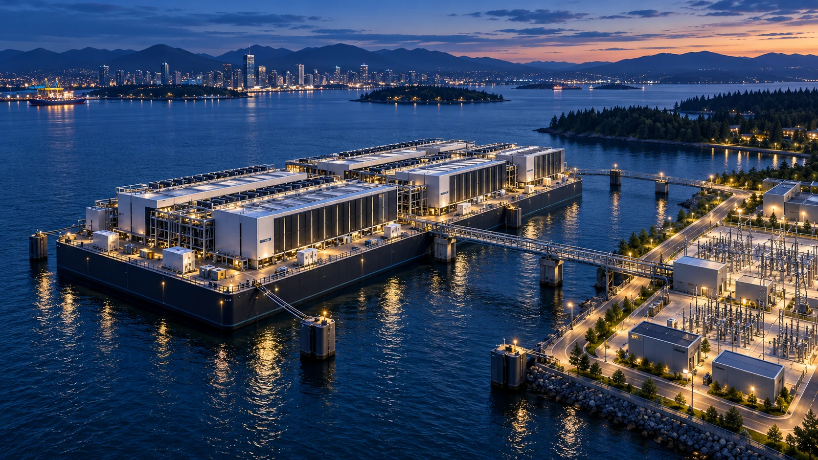
Start with the constraint the water actually removes
A floating data center deserves consideration when a usable waterfront location offers a measurable advantage: scarce developable land, an industrial berth near demand, a compatible power strategy, or a delivery opportunity that a conventional site cannot match. Begin with the required information technology (IT) load, service date, resilience, customer connectivity, and operating life. Then identify exactly which constraint floating removes. If the limiting factor is an unavailable grid connection, moving the halls onto water leaves that problem unresolved unless a credible alternative supply is included.
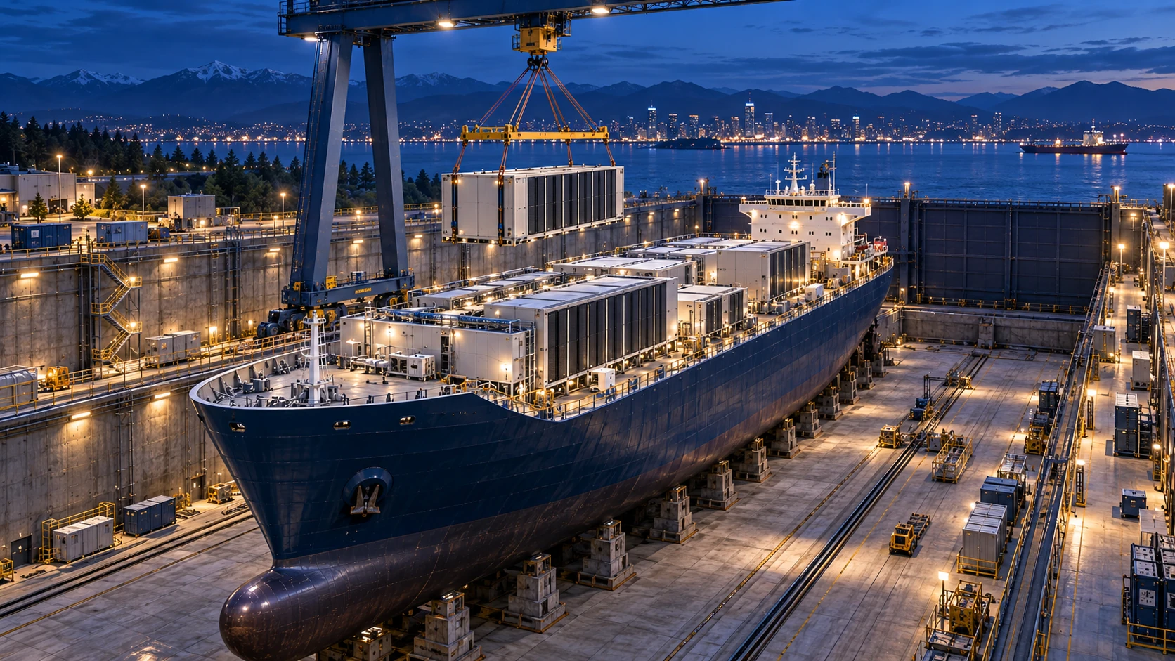
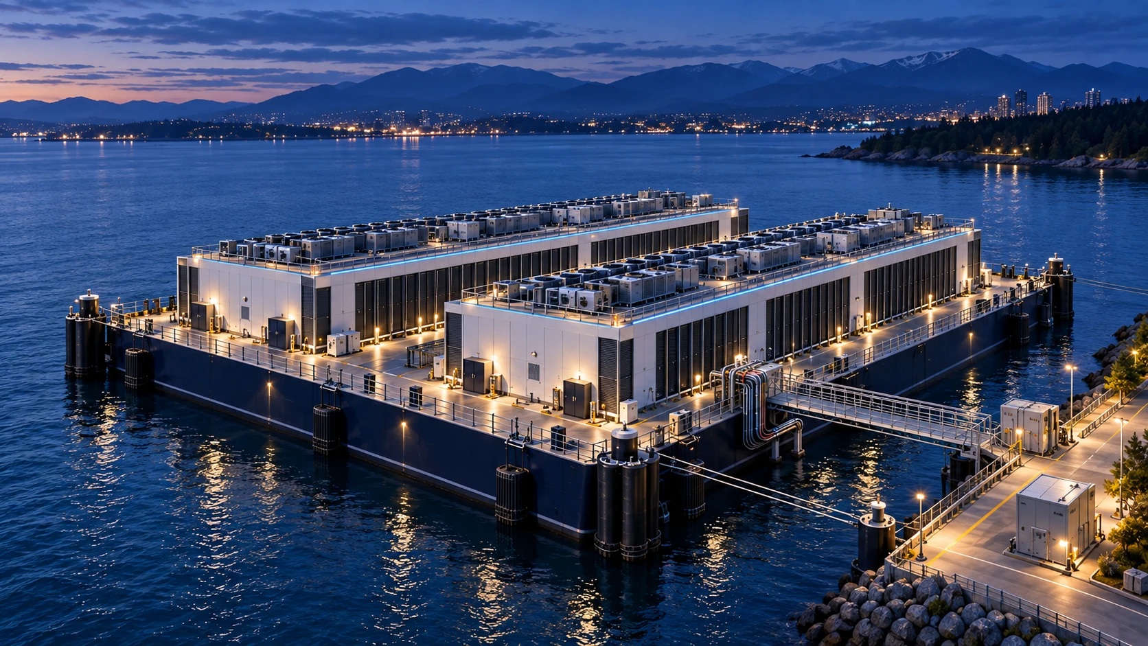
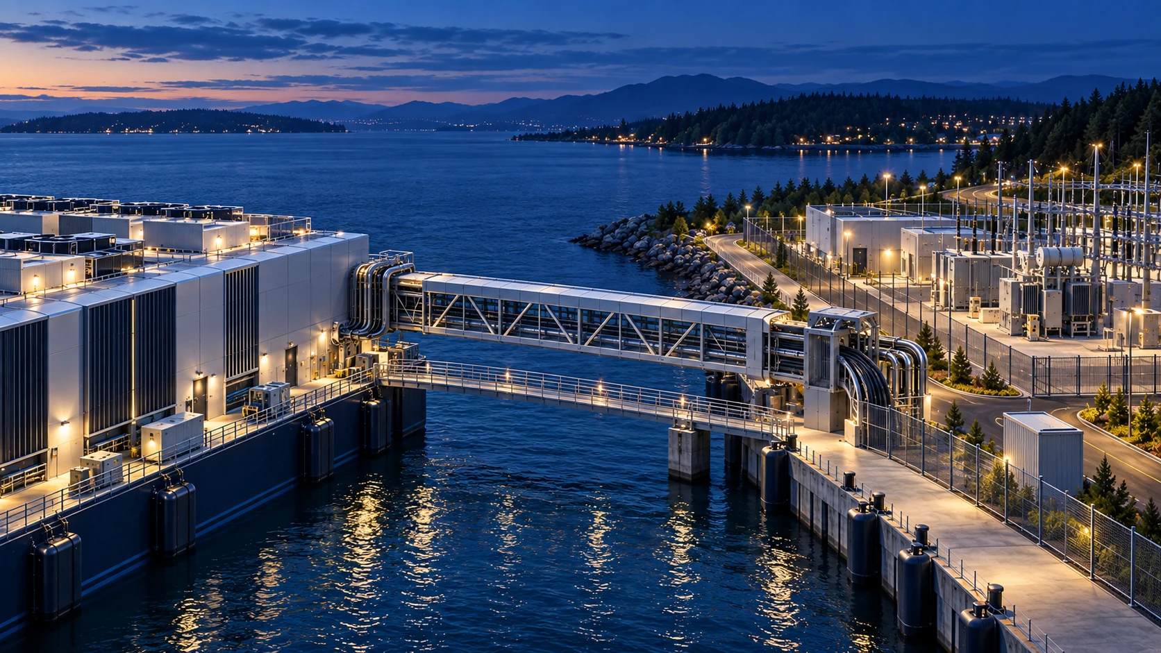
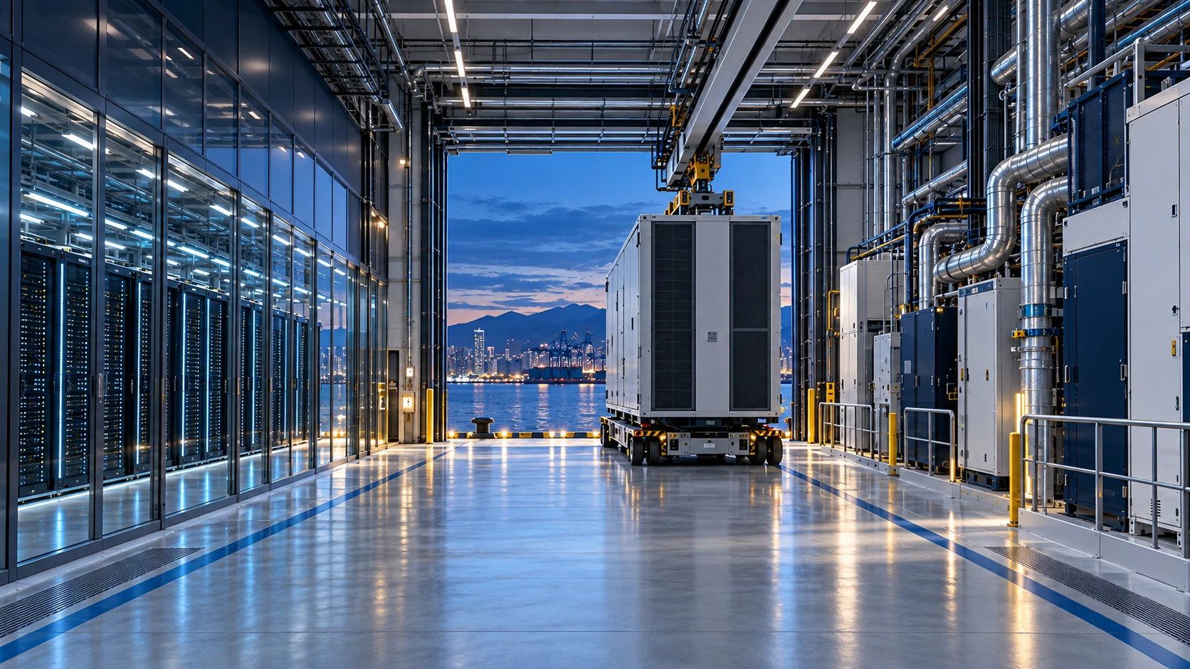
The following framework is DCFR’s planning assessment. All five illustrations are AI-generated architectural concepts; they do not depict the named projects or establish engineered capacity, approved marine arrangements, or operating performance.
Separate commercial facilities, proposals, and experiments
Different forms of water-based infrastructure have different evidence. A commercial berth, an announced conversion project, and a submerged research module should not be treated as interchangeable proof of readiness.
Commercial waterfront example — Nautilus, Stockton
Nautilus publishes a 6.5-megawatt (MW) critical IT offering for Stockton 1. Its specifications identify utility-fed shore infrastructure, two fiber paths, marine moorings, and river-water heat exchange with a separate closed loop serving the data halls. These are operator-reported facility specifications, not a universal performance guarantee for floating designs.
Announced vessel conversion — MOL and Kinetics
Mitsui O.S.K. Lines (MOL) announced its agreement with Kinetics on July 7, 2025. That announcement describes a retrofitted vessel, a stated data center capacity range of 20–73 MW, and a 2027 deployment target subject to feasibility and development. It considers floating power supply and grid options. The announcement supports a proposal and target; it does not establish completed operating capacity, and its capacity figure should not automatically be treated as net usable IT load.
Subsea research — Microsoft Project Natick
Microsoft’s Project Natick investigated sealed subsea modules. Microsoft reports that servers in its Northern Isles trial failed at one-eighth the rate of a land-based control group. That result belongs to the specific experiment. It does not demonstrate that an occupied ship or barge will have the same reliability, economics, or maintenance model.
Ship conversion starts with the hull and the operating plan
A reused ship can offer existing structure and access to established shipyard capabilities. It also brings inherited geometry and condition. Before valuing that advantage, obtain a vessel survey and test remaining service life, corrosion, watertight boundaries, stability, deck loading, clear height, vibration, and the arrangement of technical spaces. A commercial cargo vessel and a retired warship present very different starting conditions. The proposed installation must reconcile data hall loads, batteries, electrical rooms, cooling equipment, fire separation, escape routes, and equipment movement with the vessel’s structure.
Compare retention, strengthening, removal, and replacement component by component. Confirm which original systems can support the new duty rather than assuming that existing generators, ventilation, or seawater systems are suitable. Budget conversion engineering, shipyard time, inspection, surveys, and the consequences of any future dock visit.
A purpose-built barge can organize the facility around compute
A purpose-built rectangular platform gives the design team more freedom to coordinate hall geometry, structural grids, service corridors, and plant zones from the outset. That freedom is valuable when it creates repeatable spaces and straightforward installation and replacement routes. The platform must still carry its full operating load, maintain appropriate stability and freeboard, and accommodate the site’s water-level range. Increasing rooftop equipment or rack density changes more than a room layout; it can change the marine design basis.
Plan the hull, buildings, mooring system, and shore interfaces as one facility. Reserve deck space for inspection, emergency access, safe separation, and heavy equipment movement. A second barge requires its own berth, utility allocation, access, and approval assessment; expansion cannot be inferred from open water visible in a rendering.
Compare the development models
| Model | Potential advantage | Evidence needed before selection |
|---|---|---|
| Converted commercial ship | Reuse a suitable hull and shipyard production capabilities | Condition and remaining life; conversion scope; stability and loads; service access; berth and shore infrastructure |
| Purpose-built barge | Coordinate repeatable halls and marine structure around the program | Platform design; moorings; utility and access interfaces; operating limits; future maintenance |
| Submerged module | Explore sealed operation and water-based heat rejection | Retrieval and refresh model; module reliability evidence; site and environmental permissions; repair economics |
| Factory-built modules on land | Use repeatable fabrication with a conventional site operating model | Land readiness; power date; transport and crane access; foundations; site integration and commissioning |
DCFR planning comparison. Potential advantages are hypotheses to test against project evidence, not guaranteed cost or schedule outcomes.
The shore connection is part of the data center
Prepare a combined water-and-land plan showing the berth, substation, power routes, fiber entries, access roads, security boundary, fuel deliveries where needed, and emergency response arrangements. Assign an owner, design responsibility, maintenance duty, and delivery date to each interface. A floating building may reduce the hall’s land footprint while retaining substantial demand for shore infrastructure. The commercial agreement must control that supporting land and the routes connecting it.
Trace redundant services back to their actual sources. Two electrical feeders or two fiber cables can share a duct, utility bridge, landing structure, or upstream facility. Test whether one impact, fire, flood, maintenance activity, or mooring event could remove both paths. Flexible connections must be coordinated for movement, isolation, inspection, and replacement. Where floating generation is proposed, add fuel logistics, emissions, operating permissions, maintenance, and supply reliability to the same plan.
Access to water is a cooling opportunity with conditions
Choose the cooling architecture before claiming an efficiency benefit. Compare air-based heat rejection with water-assisted alternatives using the same IT load, environmental conditions, and operating limits. Where river or seawater exchanges heat with a closed facility loop, examine seasonal water temperature, sediment, debris, biological fouling, corrosion, intake availability, pumping duty, and heat-exchanger maintenance. Define what happens during an intake outage or an exceptional warm-water event.
Keep water withdrawal, water consumption, and thermal discharge separate in the evidence record. Low consumptive use does not establish low ecological impact. The U.S. Environmental Protection Agency identifies environmental harm associated with cooling water intakes, and the National Pollutant Discharge Elimination System (NPDES) regulates qualifying point-source discharges. Determine the applicable requirements with the responsible authorities for the specific intake, discharge, location, and operating conditions; proximity to water grants no automatic right to use it.
Test marine exposure and establish the approval pathway early
Define site-specific wind, waves, currents, water-level extremes, vessel wakes, collision exposure, debris, corrosion, and access conditions with marine specialists. A floating hull’s ability to rise with water does not make the shore substation, gangways, cable landings, roads, or emergency routes flood-resistant. Model the entire operating chain and identify the conditions under which access, cooling, or normal operation must be restricted.
Before committing to the berth, establish the facility’s legal and technical classification and the authorities involved. Ask which port, navigation, environmental, shoreline, building, fire, and maritime reviews apply. Determine whether flag-state or classification-society requirements are relevant to the proposed structure and operating model. Obtain an agreed responsibility matrix, inspection strategy, and emergency-response concept. These are location-specific diligence questions, not a claim that every listed regime applies to every floating facility.
Design replacement access before filling the halls
Draw a complete replacement route for the largest and heaviest items: racks, cooling distribution equipment, batteries, electrical equipment, and major mechanical plant. Check the internal aisle, doors, turns, deck structure, lifting points, laydown space, and transfer from platform to shore. Allow for an item to be disconnected and moved while adjacent systems remain available. Salt exposure, condensation control, drainage, and weather protection require deliberate treatment at service openings.
The maintenance strategy must state whether the facility remains occupied at its berth, requires periodic relocation, or needs a dock visit. Do not assume that major hull work can proceed without affecting compute service. Identify survey obligations, inspection access, replacement intervals, outage windows, temporary capacity, and customer commitments. A submerged sealed module uses a different service philosophy, potentially requiring retrieval rather than routine walk-in maintenance; its hardware refresh plan must fit that constraint.
Compare the full cost and the date of usable capacity
Compare a converted ship, a purpose-built barge, and a credible land-based option at the same usable IT load, redundancy, cooling duty, service quality, and operating period. Include the vessel or platform, conversion, berth rights, shore land, moorings, utility upgrades, fiber, marine works, approvals, commissioning, insurance, inspections, maintenance, outages, and eventual removal or disposal. Apply project-specific cost evidence and sensitivity ranges. A low hull purchase price is only one input.
Build a dependency schedule for shipyard work and shore delivery together. Usable capacity arrives only after the necessary power, connectivity, approvals, marine works, and commissioning are complete. Factory fabrication can shorten a construction activity while the project still waits for a berth or utility upgrade. Count relocation as valuable only when a suitable receiving site, towing or transport plan, permissions, outage strategy, and reconnection cost are credible.
Advance only when the floating option wins a defined comparison
Use staged decisions. First establish a plausible berth and supporting land arrangement. Next confirm a credible power-and-fiber path, screen marine and environmental constraints, and compare concept layouts. Then obtain specialist assessments, supplier input, operating assumptions, and a schedule that reaches commissioned capacity. Increase financial commitment only as the controlling uncertainties are resolved.
Floating is strongest when the site’s water access, shore infrastructure, commercial rights, and operating needs work together. If the advantage disappears after marine costs, shore works, maintenance, and approval time are included, advance the land-based alternative. The decision is a measurable capacity-delivery comparison, not a preference for an unusual building form.
Decision gates before committing to a floating site
| Gate | Required evidence | Reason to pause |
|---|---|---|
| Control the full site | Berth term, shore rights, access, utility routes, and responsibilities | A vessel is available but the supporting site is not controlled |
| Prove the service path | Power and fiber scope, dates, interfaces, and credible resilience | Nearby infrastructure is treated as committed capacity |
| Resolve the marine basis | Condition or new platform design; hazards; moorings; access limits | Hull condition, water-level range, or shared failures remain unbounded |
| Establish operations | Maintenance, inspections, replacement logistics, emergency response, and removal | Service continuity depends on untested access or relocation assumptions |
| Compare delivery and cost | Equivalent usable capacity, integrated schedule, lifecycle cost, and sensitivities | The claimed advantage excludes shore works or marine operating obligations |
Early screening checklist
What to verify before advancing this site.
- Required usable IT capacity, resilience, service date, and operating life are defined.
- Berth rights, supporting shore land, utility routes, and access are controlled.
- Ship condition or platform design is supported by marine and structural assessment.
- Power and fiber have a documented delivery path and shared failure points are identified.
- Cooling is evaluated for seasonal conditions, maintenance, and intake or discharge constraints.
- Marine hazards, operating limits, and shore flood exposure are assessed together.
- Applicable authorities, classifications, reviews, and inspections are identified.
- Heavy equipment replacement and any dock visit fit the continuity plan.
- Whole-life cost and commissioned-capacity dates are compared on an equivalent basis.
- Decommissioning, relocation assumptions, and residual obligations are included.
What DCFR would flag
Risks surfaced at the screening stage.
At the screening stage, flag a floating proposal whose claimed advantage depends on free shore infrastructure, unverified utility capacity, unlimited water use, assumed approval speed, or maintenance without operational consequences. The berth and shore systems belong inside the project boundary.
Professional confirmation required
Items requiring licensed validation.
Marine and naval-architecture specialists, structural and building-services engineers, the utility and fiber providers, port and other applicable authorities, environmental specialists, operators, insurers, and counsel must validate the project-specific design and operating basis.
Final takeaway
A floating data center becomes a credible development option when the combined vessel, berth, shore infrastructure, and operating plan deliver the required capacity more effectively than a comparable land-based facility.
Screen up to 20 candidate sites before selecting one for the full DCFR report.
Each DCFR Report Package includes a preliminary 20-site comparison PDF / export package plus one selected planning-grade feasibility report.