
DCFR Insight 18 / Envelope + Field QA
Capacity DeliveryData Center Envelope Design by Climate Zone and Firestopping Risk
A data center enclosure must respond to climate, rain, humidity, temperature, wind, snow, dust, corrosion, internal cooling, and operational pressure—then preserve those control layers through every roof, wall, louver, door, curb, penetration, and rated boundary.
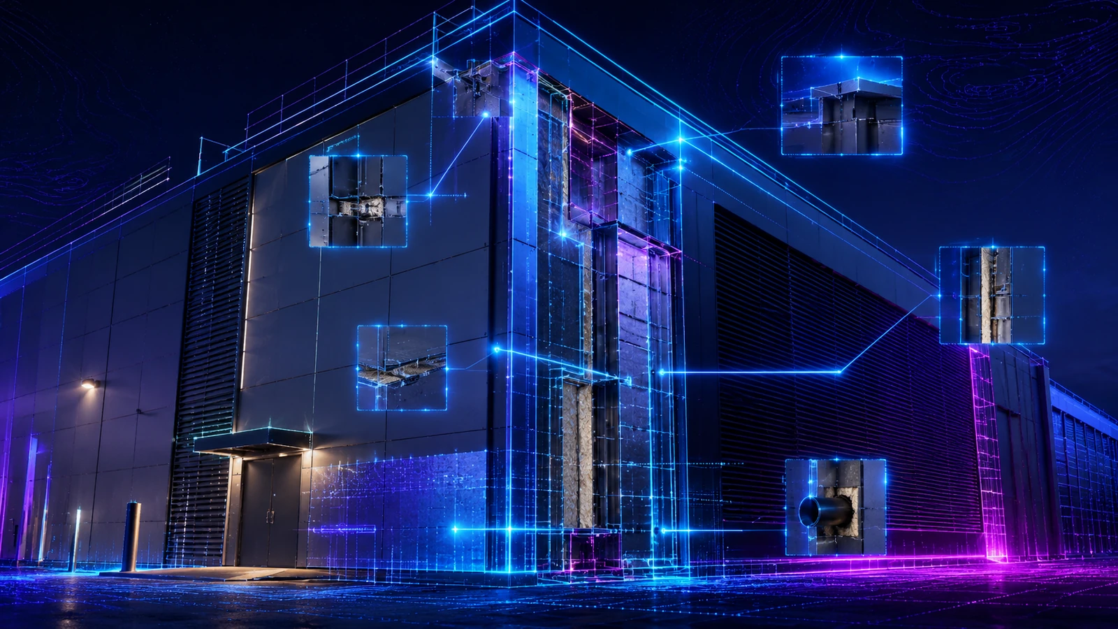
Climate zone is an envelope design input, not a specification footnote
An enclosure that performs well in one region can fail in another because heat, moisture, rain, wind, snow, solar exposure, and drying potential change the direction and intensity of the loads. The adopted energy code establishes the project climate zone; moisture regimes are commonly identified as A for moist, B for dry, and C for marine. Current code editions may include Climate Zone 0, while many projects and reference standards still organize U.S. practice around Zones 1 through 8. The project team must confirm the adopted edition and exact location before selecting insulation, vapor control, cladding, roof, sealants, and test criteria.
Data centers are not ordinary commercial buildings
Data centers are typically internal-load-dominated and may require cooling during conditions when other buildings are heating. Data halls, electrical rooms, battery rooms, offices, loading areas, and equipment vestibules can have different temperature, humidity, and pressure conditions. Large louvers, cable and busway penetrations, roof curbs, equipment doors, and yard interfaces interrupt the enclosure repeatedly. The envelope strategy must therefore use project-specific indoor design conditions and pressure relationships, not a generic office assumption.
Read every climate as thermal zone plus moisture regime
The zone number indicates thermal severity; the letter identifies moist, dry, or marine conditions. Humid and marine climates generally have higher wetting potential and lower drying potential. Hot and warm humid regions can experience inward vapor drive toward cooled interiors; cool, cold, very cold, and subarctic regions more often experience outward vapor drive and severe condensation risk from warm interior air leaking toward cold exterior layers. Air leakage usually transports far more moisture than vapor diffusion, so a continuous, testable air barrier remains fundamental in every climate.
Climate-specific wall section library
Three viable wall systems for each climate family
These diagrams show planning-level control-layer order, not permit-ready assemblies. Read every stack from exterior to interior. Final materials, thicknesses, fire ratings, attachments, joints, and vapor-control classes must be validated for the project.
Climate family 1
Hot-humid
Typical application: Climate Zones 1A–3A
Hot, moisture-laden exterior air moving toward continuously cooled interiors; intense rain and coastal corrosion may govern.
Detail 1.1
Insulated metal panel
Fast, low-joint-count enclosure
Exterior
Interior
Predominant vapor drive: exterior → interior
Why recommended for this climate
Recommended where schedule and repeatability matter. Factory insulation and sealed liner joints can combine thermal, air, and vapor control while reducing field-installed layers. Exterior joints still need drained, pressure-equalized detailing.
Critical condition
Do not assume panel joints are airtight: specify full-scale mockups, compatible sealants, corner/base/louver transitions, and corrosion class.
Detail 1.2
Ventilated rainscreen
Best drying and rain-management capacity
Exterior
Interior
Predominant vapor drive: exterior → interior
Why recommended for this climate
Recommended for high rain exposure because the cavity drains bulk water before it reaches the primary control layer. Exterior vapor control can limit inward moisture drive toward cold data halls while the interior avoids a second Class I barrier.
Critical condition
Vapor permeance and insulation type must be selected by hygrothermal analysis; detail insect screens, fire blocking, drainage, end dams, and termite exposure.
Detail 1.3
Insulated precast sandwich panel
Durable mass wall with few transitions
Exterior
Interior
Predominant vapor drive: exterior → interior
Why recommended for this climate
Recommended where impact resistance, wind exposure, acoustic mass, and long service life dominate. Continuous insulation limits thermal bridging, and an interior wythe can provide a robust air-control plane when panel joints are fully sealed.
Critical condition
Use thermally efficient connectors; design two-stage drained joints and confirm drying, sealant movement, lifting inserts, and panel-to-roof continuity.
Climate family 2
Hot-dry + mixed-dry
Typical application: Climate Zones 1B–4B
Solar gain, ultraviolet exposure, dust, large diurnal swings, sealant movement, and short but intense rain events.
Detail 2.1
Insulated metal panel
Efficient enclosure for large wall areas
Exterior
Interior
Vapor drive may reverse seasonally; prioritize drying capacity
Why recommended for this climate
Recommended for rapid deployment and controlled factory quality. Light-colored exterior skins reduce solar heat gain; engineered panel joints accommodate long-run thermal movement better than layered field assemblies when correctly detailed.
Critical condition
Specify UV- and heat-rated gaskets and sealants, dust-tight joints, slip connections, and drainage for monsoon exposure.
Detail 2.2
Ventilated rainscreen
Heat-buffering outer skin
Exterior
Interior
Vapor drive may reverse seasonally; prioritize drying capacity
Why recommended for this climate
Recommended when solar exposure and temperature swing are severe. The outer skin shades the control layers, the cavity vents absorbed heat, and a vapor-permeable air/water layer preserves bidirectional drying.
Critical condition
Engineer attachment thermal bridges and wind loads; provide dust-resistant cavity closures without blocking drainage or ventilation.
Detail 2.3
Insulated precast sandwich panel
Thermal mass + high durability
Exterior
Interior
Vapor drive may reverse seasonally; prioritize drying capacity
Why recommended for this climate
Recommended for sites needing impact resistance and temperature damping. Concrete mass moderates rapid exterior temperature swings while continuous insulation protects interior conditions and reduces heat flow.
Critical condition
Use low-conductivity ties; verify joint width and sealant geometry for thermal cycling, and protect exposed sealants from intense ultraviolet exposure.
Climate family 3
Marine + mixed-humid
Typical application: Climate Zones 3C, 4C, and mixed-humid 4A
Frequent wetting, wind-driven rain, slow drying, salt exposure where coastal, seasonal vapor reversal, and occasional freeze-thaw.
Detail 3.1
Insulated metal panel
Controlled system with rigorous joint QA
Exterior
Interior
Vapor drive: variable; preserve bidirectional drying
Why recommended for this climate
Recommended where a single-source enclosure package and fast dry-in are valuable. Factory panels reduce the number of site-applied layers, but success depends on two-stage exterior joints and verified air seals at the liner plane.
Critical condition
Upgrade coatings, clips, fasteners, and cut-edge treatment for coastal exposure; water-test representative joints and openings.
Detail 3.2
Drained + ventilated rainscreen
Preferred for persistent rain exposure
Exterior
Interior
Vapor drive: variable; preserve bidirectional drying
Why recommended for this climate
Recommended where walls remain wet for long periods. The ventilated cavity separates cladding leakage from the air/water barrier and promotes drying; vapor-open layers reduce the risk of trapping moisture during seasonal reversals.
Critical condition
Maintain positive drainage at bases and openings; use thermally broken corrosion-resistant attachments and coordinate cavity fire blocking.
Detail 3.3
Insulated precast sandwich panel
Robust rain screen through joint design
Exterior
Interior
Vapor drive: variable; preserve bidirectional drying
Why recommended for this climate
Recommended for durable, low-maintenance campuses exposed to rain and salt. Concrete provides impact and acoustic resistance; properly vented two-stage joints manage water while the inner seal maintains airtightness.
Critical condition
Do not rely on a single face seal. Provide drained joint chambers, corrosion-resistant connectors, replaceable sealants, and protected base details.
Climate family 4
Cool, cold, very cold + arctic
Typical application: Climate Zones 5–8
Warm interior air exfiltration toward cold surfaces, frost accumulation, thermal bridges, snow/ice, low-temperature installation, and limited drying.
Detail 4.1
Insulated metal panel
Continuous factory insulation with minimal joints
Exterior
Interior
Predominant vapor drive: interior → exterior
Why recommended for this climate
Recommended for repeatable high-R enclosure zones when panel thickness, joint geometry, and interior liner continuity are engineered together. A protected service zone reduces later punctures through the interior air/vapor-control plane.
Critical condition
Model joints, girts, fasteners, base angles, and openings as thermal bridges; specify low-temperature sealants and installation limits.
Detail 4.2
Rainscreen over high continuous insulation
Best thermal-bridge control and repairability
Exterior
Interior
Predominant vapor drive: interior → exterior
Why recommended for this climate
Recommended where condensation and thermal bridges are the primary risks. Sufficient exterior continuous insulation keeps the sheathing warmer, while a continuous air barrier limits moisture transport by exfiltration and the outer cavity drains incidental water.
Critical condition
The exterior-to-cavity insulation ratio and interior vapor retarder class require climate- and humidity-specific hygrothermal analysis.
Detail 4.3
Insulated precast sandwich panel
High-mass, low-penetration cold-climate wall
Exterior
Interior
Predominant vapor drive: interior → exterior
Why recommended for this climate
Recommended for severe climates where robust air control, impact resistance, and few penetrations outweigh heavier erection logistics. Continuous insulation and thermally efficient ties reduce cold interior surfaces.
Critical condition
Analyze panel ties, foundations, roof connections, openings, and joints in two dimensions; protect the air layer from future services and low-temperature sealant failures.
Planning note: confirm the adopted code and climate zone, interior temperature and humidity, wind and rain exposure, required fire propagation testing, corrosion class, acoustics, structural loads, and manufacturer limitations. Complete hygrothermal and thermal-bridge analysis before fixing the assembly.
Climate Zone 1 — very hot: control solar load, humid-air intrusion, and wind-driven rain
Zone 1 is cooling-dominated and may be humid, tropical, coastal, or dry depending on location. In 1A or tropical conditions, the exterior air can remain hot and moisture-laden while the data center interior is continuously cooled. Prioritize exterior rain control, drained joints and openings, a highly continuous air barrier, corrosion-resistant materials, and vapor-control placement that does not trap inward-driven moisture against cold interior finishes. Roofs need high solar reflectance, robust drainage and overflow, wind-uplift design, and hurricane or severe-wind detailing where applicable. Louvers require tested wind-driven-rain performance, drainage, and serviceable filtration. In dry Zone 1 conditions, solar intensity, UV, dust, thermal cycling, sealant durability, and filtration become more dominant, while monsoon events can still create short periods of intense rain.
Climate Zone 2 — hot: balance year-round cooling with occasional cold-weather reversals
Zone 2 remains cooling-dominated but may experience more seasonal variation than Zone 1. In 2A, control humid-air infiltration, wind-driven rain, corrosion, and inward vapor drive. In 2B, emphasize solar reflectance, continuous insulation, dust exclusion, UV-resistant membranes and sealants, and movement at long metal-panel runs. Because some locations experience occasional cold periods, avoid assemblies that can dry in only one direction unless hygrothermal analysis supports them. Roof-to-wall and louver details should be able to manage both intense rain and temperature cycling.
Climate Zone 3 — warm: design for mixed seasonal loads and regional extremes
Zone 3 can be warm-humid, warm-dry, or marine. Heating is no longer negligible, so vapor direction can reverse seasonally. Avoid indiscriminate Class I vapor barriers on both sides of an assembly; preserve drying potential and use hygrothermal analysis for high-R or low-permeance walls. In 3A, rain, humidity, termites, corrosion, and inward vapor drive remain important. In 3B, solar, dust, large diurnal swings, and sealant movement dominate. In 3C, marine air, frequent wetting, salt exposure, and slow drying favor robust rainscreen drainage, corrosion resistance, and careful joint design.
Climate Zone 4 — mixed: prioritize bidirectional drying and transition durability
Zone 4 is the most unforgiving of copied details because it can experience meaningful heating, cooling, rain, humidity, and freeze-thaw. The enclosure must tolerate vapor-drive reversal. Continuous exterior insulation can reduce thermal bridges and keep condensing surfaces warmer, while the air barrier must remain continuous through slabs, roofs, openings, and equipment interfaces. In 4A, manage mixed-humid wetting and summer inward drive; in 4B, address dry-climate solar and temperature swings; in 4C, such as much of the maritime Pacific Northwest, prioritize frequent rain, low drying potential, corrosion, drained and ventilated cavities where appropriate, roof drainage, and protected base-of-wall details. A marine climate is not necessarily extremely cold, but it can be exceptionally punishing to joints that remain wet.
Climate Zone 5 — cool: control exfiltration, thermal bridges, snow, and freeze-thaw
Zone 5 shifts the dominant winter vapor drive outward. Warm interior air leaking through joints can condense at cold sheathing, metal skins, fasteners, or roof layers. Airtightness, exterior continuous insulation, thermally broken attachments, and project-specific interior vapor control become more important. Roofs and parapets must address snow, ice, freeze-thaw, overflow, membrane terminations, and winter construction. Door frames, louver perimeters, panel bases, and slab edges deserve thermal and condensation analysis because metal components can create cold interior surfaces near critical equipment.
Climate Zone 6 — cold: make air control and exterior insulation non-negotiable
In Zone 6, uncontrolled exfiltration can rapidly create hidden condensation, frost, corrosion, and insulation damage. Use a continuous air barrier with defined ownership and quantitative testing; maintain substantial insulation continuity outside or around structural and metal framing; and select vapor control based on the full assembly and indoor humidity. Limit unnecessary penetrations, design service cavities where practical, and detail roof curbs, parapets, doors, louvers, and equipment openings to prevent interior moisture from reaching cold layers. Snow drifting, ice, low-temperature sealant installation, and freeze protection at drains and scuppers require explicit detailing and sequencing.
Climate Zone 7 — very cold: simplify the enclosure and minimize thermal shortcuts
Zone 7 requires high thermal resistance, aggressive thermal-bridge control, very reliable air and vapor control, and materials that remain flexible and bond at low temperatures. Reduce the number of wall and roof interruptions; group penetrations; use thermally broken doors and subframes; and keep structural steel, clips, girts, and embeds from bypassing insulation. Roof geometry must account for snow accumulation, drifting around screens and penthouses, ice, wind scour, and safe maintenance access. Construction moisture must be managed because drying after enclosure can be extremely slow.
Climate Zone 8 — subarctic/arctic: design for extreme cold, limited drying, and maintainability
Zone 8 combines extreme heating demand, very low exterior temperatures, snow and ice, seasonal construction constraints, and difficult repair access. Favor compact geometry, minimal openings, redundant air-control detailing, thick continuous insulation, robust interior vapor control where analysis supports it, and service zones that allow utilities to pass without puncturing the primary control layers repeatedly. Select membranes, gaskets, coatings, fasteners, and sealants for verified low-temperature performance. Plan snow storage, drifting, roof access, freeze-resistant drainage, and inspection from the beginning. Small air leaks can become major frost reservoirs in these conditions.
Roof strategy changes by climate—but roof-to-wall continuity is always the first review gate
Hot climates emphasize solar reflectance, membrane temperature, UV, wind uplift, and intense rain. Marine and humid climates emphasize drainage, overflow, protected terminations, and drying. Cold climates add snow, ice, vapor drive, freeze-thaw, low-temperature materials, and drift loads. At every location, trace roof membrane, air barrier, vapor control, insulation, structure, and drainage continuously through parapets, copings, curbs, scuppers, joints, and wall transitions. Coordinate every roof penetration before release; late penetrations create leakage paths, warranty disputes, and inaccessible repairs.
Wall-base and foundation details must connect envelope and civil design
The panel base is affected by finished grade, splashback, snow, deicing salts, irrigation, site drainage, slab-edge thermal bridges, capillary rise, pest control, and equipment-yard spills. Hot-humid regions need drainage and termite-aware detailing; marine regions need corrosion and persistent-wetting resistance; cold regions need frost, snow, salt, and slab-edge condensation control. Keep vulnerable panel cores and sealants away from standing water, provide replaceable flashings where practical, and coordinate the base detail with actual civil elevations rather than a generic datum.
Louvers and large openings are miniature building envelopes
Data centers may have large intake and exhaust openings with high airflow and strict pressure relationships. A louver must coordinate water rejection, snow or sand exclusion, drainage, pressure drop, acoustics, corrosion, bird/insect screens, dampers, controls, structure, maintenance, and the adjacent air barrier. Climate affects the dominant test: wind-driven rain in humid and marine regions; sand and dust in dry regions; snow and icing in cold regions; salt and corrosion at coasts. Heads, jambs, sills, end dams, subframes, and interior drainage paths must be drawn as a complete system.
Firestopping fails where the penetration strategy is not designed
A rated wall can be correct while the completed boundary is not. Build a penetration matrix by rated assembly, penetrating item, size, annular space, sleeve, insulation, movement, required rating, listed system, installer, inspection, and future change. Coordinate cable tray, busway, conduit banks, pipes, ducts, dampers, structural members, head-of-wall joints, and modular interfaces. Group penetrations where it improves control, reserve future capacity deliberately, and limit engineering judgments to controlled exceptions rather than using them as a substitute for tested-system planning.
Envelope and fire barriers must be reviewed together at equipment-yard interfaces
Generator, transformer, electrical, cooling, fuel, and battery zones create penetrations, heat, exhaust, vibration, sound, impact, drainage, fire exposure, and maintenance at the building edge. Review exterior-wall rating and opening exposure, intake/exhaust relationships, acoustic assemblies, corrosion, spill paths, removable panels, door swings, bollards, clearances, and replacement routes. A climate-appropriate wall can still fail operationally if the adjacent yard is not coordinated.
Mockups must reproduce the risky interface and the local weather exposure
Do not approve only a flat panel sample. Build representative multi-trade mockups for roof-to-wall, panel base, corner, louver, door, curb, penetration, firestop, and dissimilar-material transitions. The mockup should use the proposed substrate, fasteners, membranes, sealants, primers, insulation, firestop systems, tolerances, and installation sequence. Test air and water performance where appropriate, document adhesion and repair procedures, and include low- or high-temperature installation limits relevant to the project climate.
Field QA must verify continuity before concealment
Define air-barrier tests, chamber or whole-building testing as appropriate, water testing at openings and interfaces, roof observations, sealant adhesion tests, infrared or thermographic review, firestop special inspection, photo documentation, and hold points before concealment. Assign responsibility for every control layer and transition. Quantity-based inspection sampling should increase at first installations, trade changes, repairs, and recurring failure locations.
Closeout must preserve enclosure intelligence for future operations
Turnover should include approved assemblies and details, mockup records, test reports, leak and repair logs, warranties, listed firestop systems, engineering judgments, penetration labels, inspection records, as-built locations, photographs, spare materials, cleaning and maintenance instructions, and limits on future penetrations. Operations teams should be able to understand how the building stays dry, airtight, insulated, and fire-resistive long after the original trades leave.
Climate-zone envelope strategy for data centers
| Zone | Typical thermal character | Dominant enclosure risks | Planning-grade strategy | Details to intensify |
|---|---|---|---|---|
| 1 — Very hot | Extreme cooling; humid/tropical or dry variants | Inward vapor drive, wind-driven rain, solar/UV, corrosion or dust | Continuous exterior rain/air control; reflective roof; climate-specific vapor strategy; robust filtration/corrosion package | Louvers, roof edges, doors, panel joints, coastal fasteners, hurricane/wind zones |
| 2 — Hot | Cooling-dominated with some seasonal reversal | Humidity or dry heat, rain events, UV, thermal cycling | Preserve drying; continuous insulation/air barrier; high-performance roof and joints | Roof-to-wall, long panel runs, openings, sealants, dust/rain exclusion |
| 3 — Warm | Heating and cooling; A/B/C variants | Seasonal vapor reversal, rain, marine wetting, diurnal movement | Bidirectional drying; drained assemblies; climate-specific corrosion and solar control | Bases, rainscreen cavities, corners, dissimilar materials, air-barrier transitions |
| 4 — Mixed | Balanced heating/cooling; humid, dry or marine | Vapor reversal, frequent wetting, freeze-thaw, low drying in marine locations | Exterior insulation; robust air/water continuity; avoid double vapor barriers; hygrothermal review | Seattle-like 4C rain exposure, parapets, slab edges, openings, sealant durability |
| 5 — Cool | Heating-dominated with warm summers | Exfiltration condensation, snow/ice, thermal bridges, freeze-thaw | Strong airtightness; exterior CI; project-specific interior vapor control | Metal frames, louvers, doors, roof drains, parapets, slab edges |
| 6 — Cold | Severe winter and outward vapor drive | Frost in assemblies, cold-surface condensation, snow drift, low-temp installation | Quantitative air testing; high CI; minimized penetrations; cold-rated materials | Curbs, penetrations, door thresholds, roof/wall transitions, drains |
| 7 — Very cold | Very high heating and short drying season | Extreme thermal bridging, frost reservoirs, heavy snow/ice | Simplified enclosure; grouped penetrations; aggressive thermal breaks and vapor/air control | Structural clips, equipment openings, service penetrations, snow-drift zones |
| 8 — Subarctic/arctic | Extreme cold and constrained construction season | Very limited drying, material brittleness, severe snow/ice and repair difficulty | Compact form; redundant air control; thick CI; service cavity; low-temp-qualified systems | All joints and openings, roof access/drainage, snow storage, maintainable inspection points |
High-risk envelope and fire-barrier interfaces
| Interface | Primary failure mode | Climate-sensitive questions | Required evidence |
|---|---|---|---|
| Roof-to-wall/parapet | Leakage, wind damage, condensation, ice and inaccessible repair | Rain intensity, uplift, snow/drift, vapor direction, membrane temperature | Coordinated detail, mockup/test, observations, warranty |
| Panel base/foundation | Trapped water, corrosion, core damage, thermal bridge | Grade, splash, snow, salt, termites, frost and drainage | Civil-coordinated detail, sample, inspection and repair log |
| Louvers/openings | Water/snow/dust entry, recirculation, acoustic leakage | Wind-driven rain, icing, sand, salt, prevailing wind | Test data, shop drawings, drainage and access verification |
| Doors/removable panels | Water/air leakage, cold surfaces, security and blocked replacement | Threshold snow/rain, thermal break, gasket temperature range | Operational test, perimeter inspection, route confirmation |
| Roof curbs/penetrations | Membrane and air-barrier discontinuity | Snow, ponding, vapor drive, movement and access | Pre-coordinated penetration plan, field observation, test |
| Rated penetrations/joints | Unlisted or inaccessible firestop and loss of continuity | Movement, insulation, environmental exposure and future change | Penetration matrix, listed systems, labels, special inspection |
| Equipment-yard wall | Heat, exhaust, noise, fire, drainage, impact and corrosion | Climate plus generator/cooling/transformer/fuel exposure | Clearance/access review, assembly confirmation, as-built documentation |
Capacity-delivery review checklist
What to verify before the next release gate.
- Adopted code edition, exact climate zone and A/B/C moisture regime confirmed
- Indoor temperature, humidity, pressure and room-specific conditions documented
- Water, air, vapor, thermal, structural and fire-control layers traced continuously
- Zone-specific roof, wall, base, opening, louver and corrosion strategies defined
- Thermal bridges and condensation risk checked at metal frames, clips, doors and penetrations
- Roof drainage, overflow, snow/ice, wind and maintenance access coordinated
- Panel bases tied to actual grades, drainage, snow, salt, splash and site exposure
- Penetration and firestop matrix linked to listed systems and future capacity
- Equipment-yard heat, exhaust, sound, fire, spill and replacement interfaces reviewed
- Multi-trade mockups reproduce the highest-risk local climate interfaces
- Air/water/enclosure tests and firestop inspections scheduled before concealment
- Closeout preserves tests, repairs, warranties, firestop records and as-built intelligence
What DCFR would flag
Delivery risks that should be visible early.
DCFR would flag copied envelope details that ignore climate zone and moisture regime, generic vapor-barrier notes, discontinuous air and thermal layers, under-designed louvers and bases, equipment-yard interfaces treated separately from the wall, firestopping without a penetration matrix, and QA plans that test products rather than constructed transitions.
Professional confirmation required
Items requiring project-specific validation.
Final climate classification, energy-code requirements, hygrothermal behavior, air/vapor strategy, insulation, condensation control, structural attachment, wind and snow loads, rain and flood exposure, corrosion, materials, fire ratings, listed penetration systems, testing, inspection, warranties, and acceptance require confirmation by the Architect and Engineers of Record, envelope and firestopping specialists, manufacturers, qualified installers, testing agencies, contractors, insurer, owner, commissioning team, and AHJ.
Final takeaway
The fastest durable enclosure is not a universal panel detail—it is a climate-specific control-layer system whose transitions, penetrations, tests, ownership, and closeout evidence are resolved before repetitive installation begins.
Surface site, code, utility, and delivery risk before it becomes expensive.
DCFR converts early assumptions into planning-grade flags, confirmation registers, and decision-ready feasibility outputs.